
How to Use TPS2116 Power Multiplexer Carrier (USB-C): Examples, Pinouts, and Specs
 Design with TPS2116 Power Multiplexer Carrier (USB-C) in Cirkit Designer
Introduction
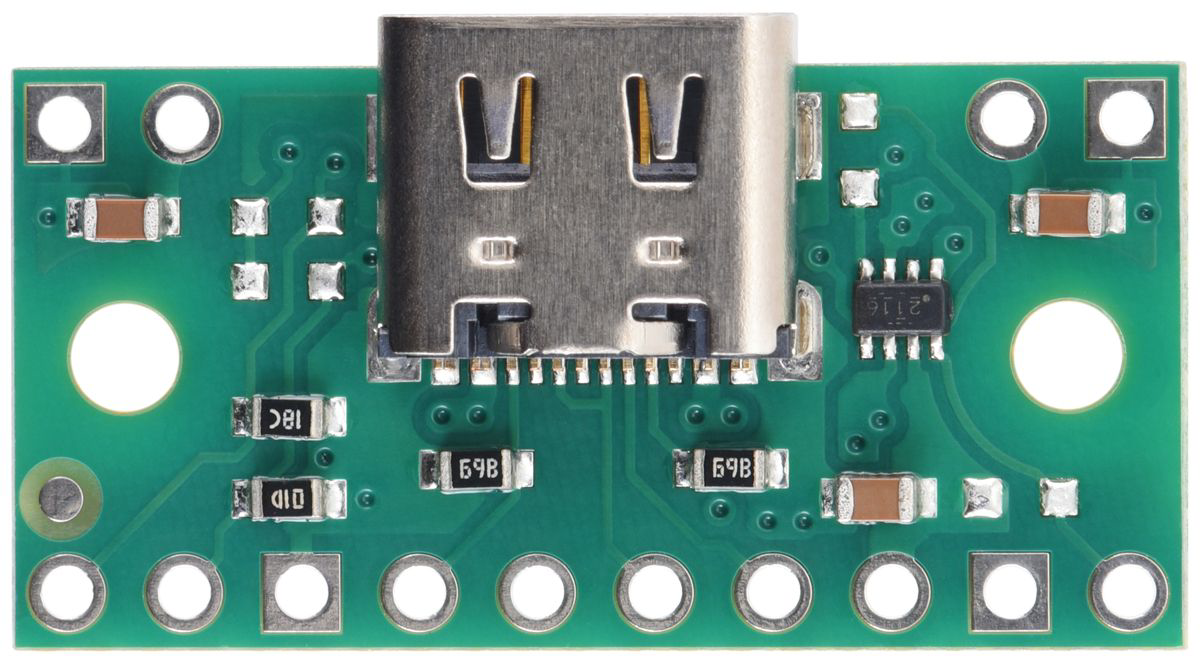
The TPS2116 Power Multiplexer Carrier (USB-C), manufactured by Pololu (Part ID: 0J15947), is a versatile power management component designed for seamless switching between two power sources. This carrier board integrates the Texas Instruments TPS2116 power multiplexer IC, which ensures reliable and efficient power delivery for USB-C applications. With its low on-resistance and robust power path management, the TPS2116 is ideal for portable devices, battery-powered systems, and applications requiring automatic power source selection.
Explore Projects Built with TPS2116 Power Multiplexer Carrier (USB-C)
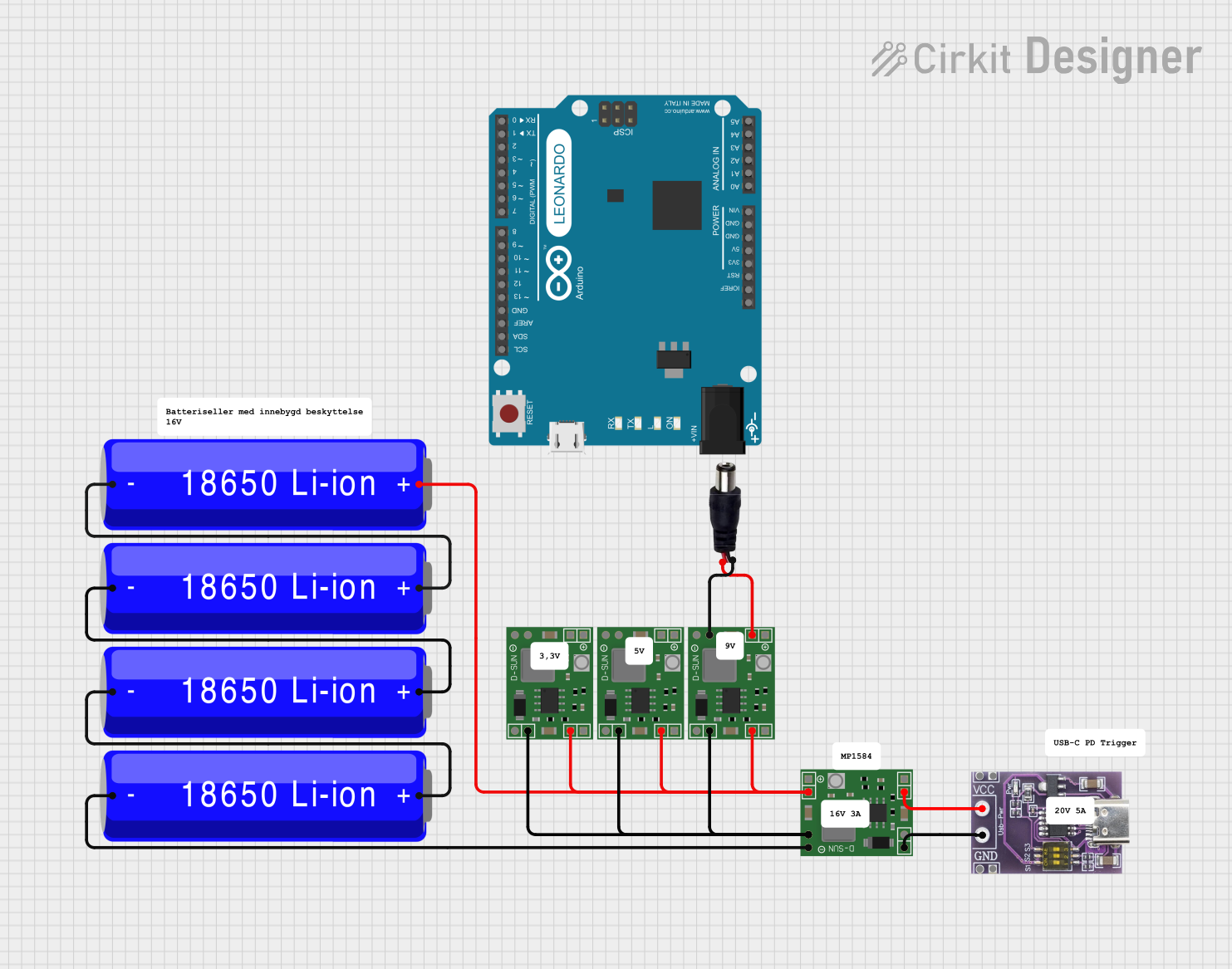 Open Project in Cirkit Designer
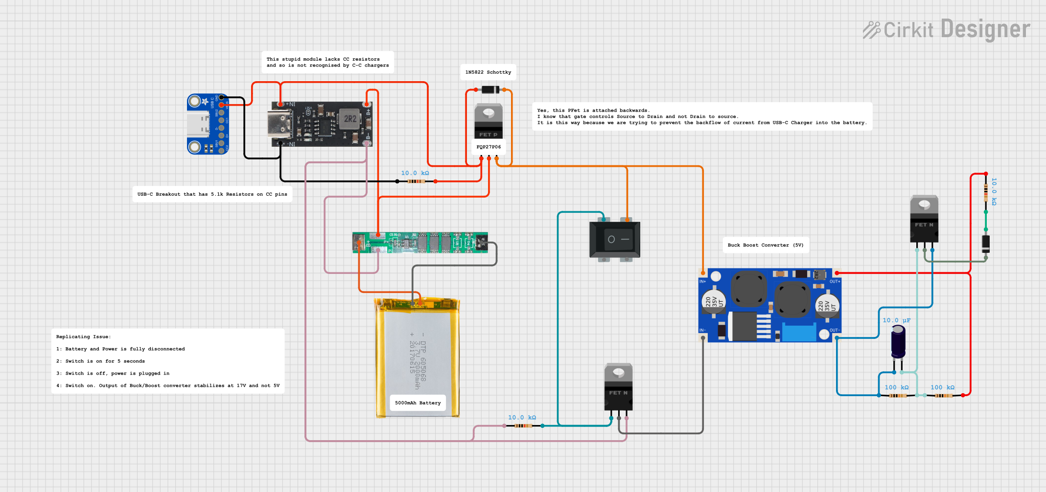 Open Project in Cirkit Designer
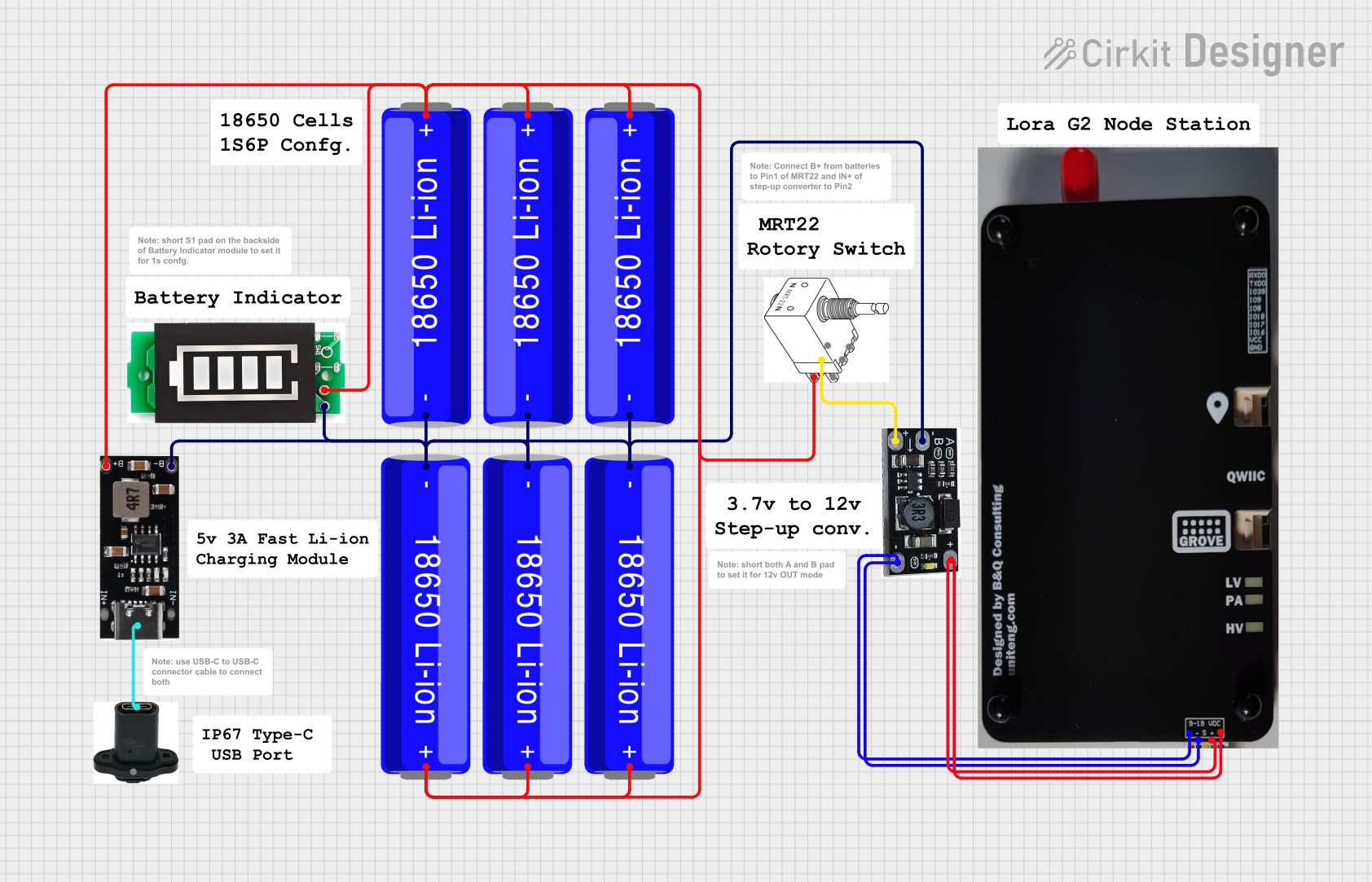 Open Project in Cirkit Designer
 Open Project in Cirkit Designer
Explore Projects Built with TPS2116 Power Multiplexer Carrier (USB-C)
Open Project in Cirkit DesignerOpen Project in Cirkit DesignerOpen Project in Cirkit DesignerOpen Project in Cirkit DesignerCommon Applications
- USB-C powered devices with backup power sources
- Battery-powered systems with USB charging
- Portable electronics requiring seamless power switching
- Embedded systems and microcontroller projects
- Power redundancy in critical applications
Technical Specifications
The following table outlines the key technical details of the TPS2116 Power Multiplexer Carrier:
| Parameter | Value |
|---|---|
| Input Voltage Range | 2.8 V to 22 V |
| Output Voltage Range | 2.8 V to 22 V |
| Maximum Output Current | 2 A (continuous) |
| On-Resistance (RON) | 50 mΩ (typical) |
| Control Logic Voltage | 1.8 V to 5.5 V |
| Operating Temperature Range | -40°C to +125°C |
| Dimensions | 0.6" × 0.8" (15 mm × 20 mm) |
| Weight | 0.6 g |
Pin Configuration and Descriptions
The TPS2116 Power Multiplexer Carrier has the following pinout:
| Pin | Name | Description |
|---|---|---|
| 1 | VIN1 | Primary power input (2.8 V to 22 V). Connect to the first power source. |
| 2 | VIN2 | Secondary power input (2.8 V to 22 V). Connect to the backup power source. |
| 3 | GND | Ground connection. |
| 4 | VOUT | Output voltage (connected to the selected power source). |
| 5 | EN | Enable pin. Drive high to enable the output; drive low to disable. |
| 6 | SEL | Source selection pin. Drive high to select VIN2; drive low to select VIN1. |
| 7 | STAT | Status output pin. Indicates the active power source (logic high or low). |
Usage Instructions
How to Use the Component in a Circuit
Power Source Connections:
- Connect the primary power source to the
VIN1pin. - Connect the secondary (backup) power source to the
VIN2pin. - Ensure both power sources are within the input voltage range (2.8 V to 22 V).
- Connect the primary power source to the
Output Connection:
- Connect the load to the
VOUTpin. The output voltage will match the selected input source.
- Connect the load to the
Control Pins:
- Use the
SELpin to manually select the active power source:- Drive
SELlow to selectVIN1. - Drive
SELhigh to selectVIN2.
- Drive
- Use the
ENpin to enable or disable the output:- Drive
ENhigh to enable the output. - Drive
ENlow to disable the output.
- Drive
- Use the
Status Monitoring:
- The
STATpin provides a logic signal indicating the active power source:- Logic high indicates
VIN2is active. - Logic low indicates
VIN1is active.
- Logic high indicates
- The
Important Considerations and Best Practices
- Input Voltage Levels: Ensure both power sources are within the specified voltage range to avoid damage to the component.
- Current Limitations: Do not exceed the maximum continuous output current of 2 A.
- Thermal Management: Operate the component within the specified temperature range (-40°C to +125°C) to ensure reliable performance.
- Decoupling Capacitors: Add appropriate decoupling capacitors (e.g., 10 µF) near the input and output pins to reduce noise and improve stability.
- ESD Protection: Use external ESD protection if the component is exposed to high static environments.
Example: Using with an Arduino UNO
The TPS2116 can be used with an Arduino UNO to manage power sources for the microcontroller. Below is an example code snippet to control the SEL and EN pins:
// Define pin connections
const int selPin = 7;  // SEL pin connected to Arduino digital pin 7
const int enPin = 8;   // EN pin connected to Arduino digital pin 8

void setup() {
  // Initialize pins as outputs
  pinMode(selPin, OUTPUT);
  pinMode(enPin, OUTPUT);

  // Enable the TPS2116 output
  digitalWrite(enPin, HIGH);

  // Select VIN1 as the active power source
  digitalWrite(selPin, LOW);
}

void loop() {
  // Example: Toggle between power sources every 5 seconds
  digitalWrite(selPin, HIGH);  // Select VIN2
  delay(5000);                 // Wait for 5 seconds
  digitalWrite(selPin, LOW);   // Select VIN1
  delay(5000);                 // Wait for 5 seconds
}
Troubleshooting and FAQs
Common Issues and Solutions
No Output Voltage:
- Cause: The
ENpin is not driven high. - Solution: Ensure the
ENpin is connected to a logic high signal to enable the output.
- Cause: The
Incorrect Power Source Selection:
- Cause: The
SELpin is not configured correctly. - Solution: Verify the logic level on the
SELpin. Drive it high forVIN2or low forVIN1.
- Cause: The
Overheating:
- Cause: Excessive current draw or operation outside the specified voltage range.
- Solution: Ensure the load does not exceed 2 A and the input voltage is within 2.8 V to 22 V.
Noise or Instability:
- Cause: Insufficient decoupling capacitors.
- Solution: Add decoupling capacitors (e.g., 10 µF) near the input and output pins.
FAQs
Q1: Can the TPS2116 handle reverse polarity on the input?
A1: No, the TPS2116 does not have built-in reverse polarity protection. Use external protection diodes if reverse polarity is a concern.
Q2: What happens if both power sources are active?
A2: The active power source is determined by the logic level on the SEL pin. Ensure proper configuration of the SEL pin to avoid conflicts.
Q3: Can I use the TPS2116 with voltages below 2.8 V?
A3: No, the minimum input voltage is 2.8 V. Operating below this voltage may result in unreliable performance.
Q4: Is the TPS2116 suitable for hot-swapping applications?
A4: Yes, the TPS2116 is designed to handle seamless switching between power sources, making it suitable for hot-swapping scenarios.