How to Use 8051 Microcontroller : Examples, Pinouts, and Specs
Introduction
The Atmel 8051 Microcontroller is a widely used 8-bit microcontroller that integrates built-in RAM, ROM, and I/O ports. It is a versatile component commonly employed in embedded systems for various applications, including industrial automation, consumer electronics, and automotive systems. The 8051 microcontroller is known for its simplicity, reliability, and ease of use, making it a popular choice for both beginners and experienced developers.
Explore Projects Built with 8051 Microcontroller
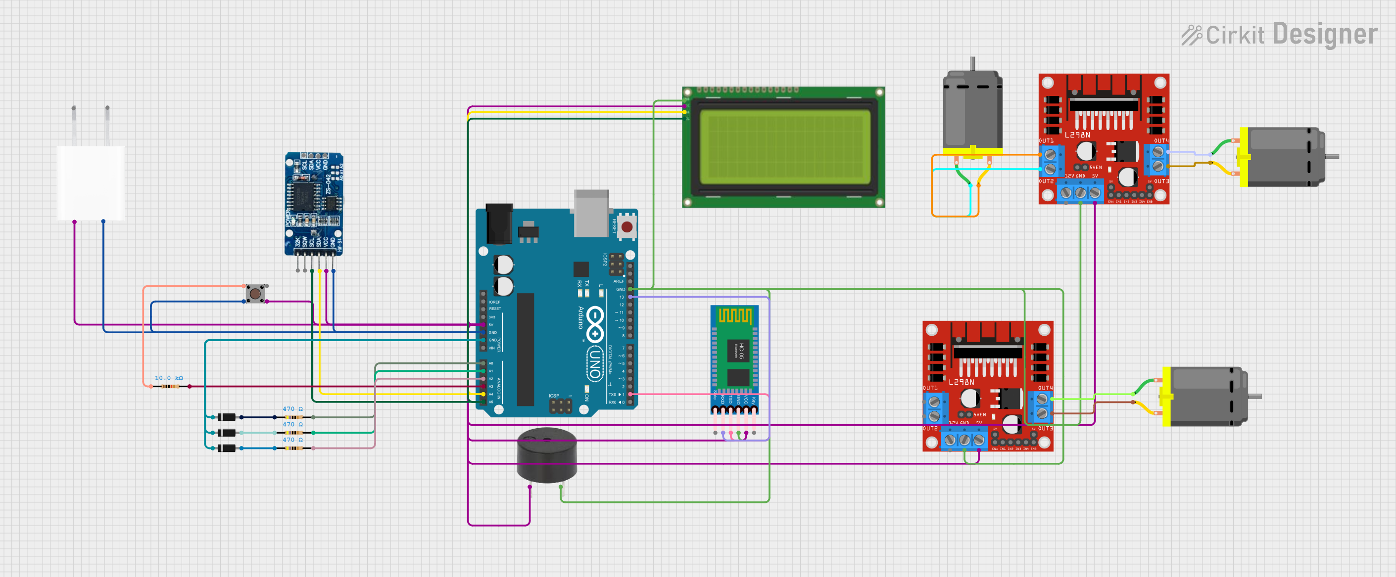
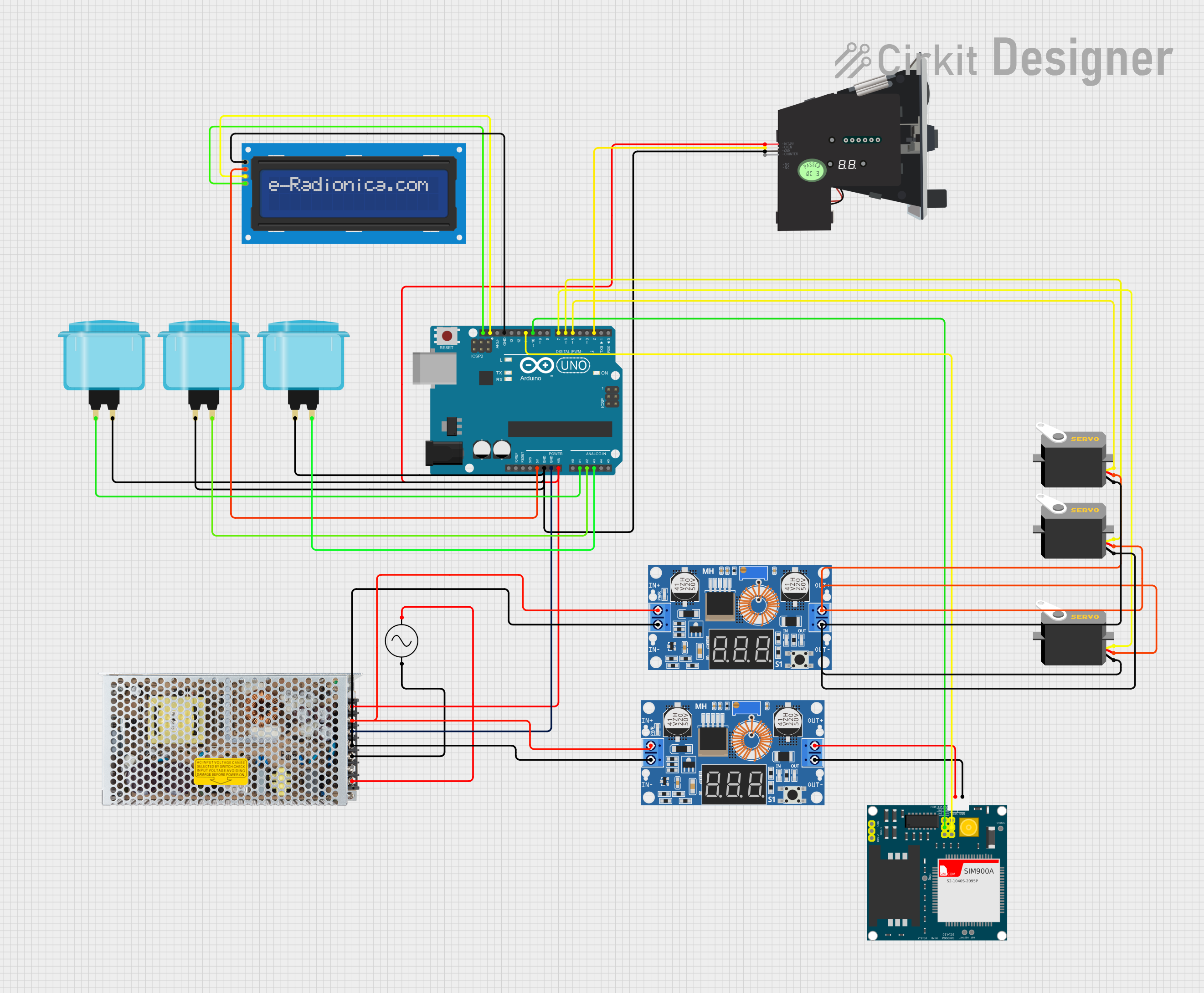
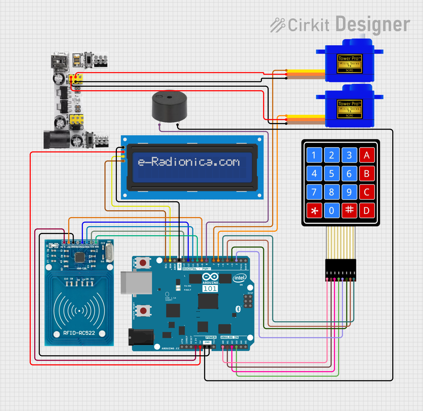
Explore Projects Built with 8051 Microcontroller
Technical Specifications
Key Technical Details
| Parameter | Value |
|---|---|
| Manufacturer | Atmel |
| Part ID | 8051 |
| Architecture | 8-bit |
| Operating Voltage | 4.0V to 5.5V |
| Clock Speed | Up to 12 MHz |
| RAM | 128 bytes |
| ROM | 4 KB |
| I/O Ports | 4 (each 8-bit wide) |
| Timers | 2 (16-bit) |
| Serial Communication | UART |
| Interrupts | 5 |
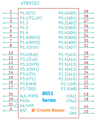
Pin Configuration and Descriptions
| Pin No. | Pin Name | Description |
|---|---|---|
| 1 | P1.0 | Port 1.0 (General-purpose I/O) |
| 2 | P1.1 | Port 1.1 (General-purpose I/O) |
| 3 | P1.2 | Port 1.2 (General-purpose I/O) |
| 4 | P1.3 | Port 1.3 (General-purpose I/O) |
| 5 | P1.4 | Port 1.4 (General-purpose I/O) |
| 6 | P1.5 | Port 1.5 (General-purpose I/O) |
| 7 | P1.6 | Port 1.6 (General-purpose I/O) |
| 8 | P1.7 | Port 1.7 (General-purpose I/O) |
| 9 | RST | Reset |
| 10 | P3.0 | Port 3.0 (RXD) |
| 11 | P3.1 | Port 3.1 (TXD) |
| 12 | P3.2 | Port 3.2 (INT0) |
| 13 | P3.3 | Port 3.3 (INT1) |
| 14 | P3.4 | Port 3.4 (T0) |
| 15 | P3.5 | Port 3.5 (T1) |
| 16 | P3.6 | Port 3.6 (WR) |
| 17 | P3.7 | Port 3.7 (RD) |
| 18 | XTAL2 | Crystal Oscillator Input 2 |
| 19 | XTAL1 | Crystal Oscillator Input 1 |
| 20 | GND | Ground |
| 21 | P2.0 | Port 2.0 (General-purpose I/O) |
| 22 | P2.1 | Port 2.1 (General-purpose I/O) |
| 23 | P2.2 | Port 2.2 (General-purpose I/O) |
| 24 | P2.3 | Port 2.3 (General-purpose I/O) |
| 25 | P2.4 | Port 2.4 (General-purpose I/O) |
| 26 | P2.5 | Port 2.5 (General-purpose I/O) |
| 27 | P2.6 | Port 2.6 (General-purpose I/O) |
| 28 | P2.7 | Port 2.7 (General-purpose I/O) |
| 29 | PSEN | Program Store Enable |
| 30 | ALE/PROG | Address Latch Enable / Program Pulse |
| 31 | EA/VPP | External Access Enable / Programming Voltage |
| 32 | P0.7 | Port 0.7 (General-purpose I/O) |
| 33 | P0.6 | Port 0.6 (General-purpose I/O) |
| 34 | P0.5 | Port 0.5 (General-purpose I/O) |
| 35 | P0.4 | Port 0.4 (General-purpose I/O) |
| 36 | P0.3 | Port 0.3 (General-purpose I/O) |
| 37 | P0.2 | Port 0.2 (General-purpose I/O) |
| 38 | P0.1 | Port 0.1 (General-purpose I/O) |
| 39 | P0.0 | Port 0.0 (General-purpose I/O) |
| 40 | VCC | Power Supply |
Usage Instructions
How to Use the 8051 Microcontroller in a Circuit
Power Supply:
- Connect the VCC pin (Pin 40) to a 5V power supply.
- Connect the GND pin (Pin 20) to the ground of the power supply.
Clock Oscillator:
- Connect a crystal oscillator (typically 12 MHz) between XTAL1 (Pin 19) and XTAL2 (Pin 18).
- Connect two 22pF capacitors from XTAL1 and XTAL2 to the ground.
Reset Circuit:
- Connect a 10µF capacitor between the RST pin (Pin 9) and the ground.
- Connect a 10kΩ resistor between the RST pin and VCC.
- Optionally, connect a push-button switch between the RST pin and the ground for manual reset.
I/O Ports:
- Use the I/O ports (P0, P1, P2, P3) for interfacing with external devices such as LEDs, switches, sensors, and more.
Important Considerations and Best Practices
- Decoupling Capacitors: Place 0.1µF decoupling capacitors close to the VCC and GND pins to filter out noise.
- Unused Pins: Configure unused I/O pins as outputs or connect them to the ground to avoid floating states.
- Programming: Use an appropriate programmer to load the firmware into the microcontroller's ROM.
Example: Interfacing 8051 with Arduino UNO
// Example code to interface 8051 with Arduino UNO
// This code demonstrates serial communication between 8051 and Arduino

void setup() {
  Serial.begin(9600); // Initialize serial communication at 9600 baud rate
}

void loop() {
  if (Serial.available()) {
    char data = Serial.read(); // Read data from 8051
    Serial.print("Received: ");
    Serial.println(data); // Print received data to the serial monitor
  }
}
Troubleshooting and FAQs
Common Issues and Solutions
Microcontroller Not Powering On:
- Ensure the VCC and GND connections are secure.
- Check the power supply voltage (should be between 4.0V and 5.5V).
No Output from I/O Ports:
- Verify the I/O port configuration in the firmware.
- Check for any short circuits or loose connections.
Serial Communication Issues:
- Ensure the baud rate settings match between the 8051 and the connected device.
- Check the connections for the RXD and TXD pins.
FAQs
Q1: Can I use a different clock frequency for the 8051? A1: Yes, you can use different clock frequencies, but ensure it is within the specified range and adjust the firmware timing accordingly.
Q2: How do I program the 8051 microcontroller? A2: You can use an external programmer compatible with the 8051 microcontroller to load the firmware into its ROM.
Q3: Can I interface the 8051 with other microcontrollers? A3: Yes, you can interface the 8051 with other microcontrollers using serial communication, I2C, or SPI protocols.
Q4: What is the maximum current the I/O pins can source/sink? A4: The I/O pins can source/sink up to 15mA. Ensure not to exceed this limit to avoid damaging the microcontroller.
This documentation provides a comprehensive guide to understanding and using the Atmel 8051 Microcontroller. Whether you are a beginner or an experienced developer, this guide will help you effectively integrate the 8051 into your projects.