Cirkit Designer
Your all-in-one circuit design IDE
Home /
Component Documentation
How to Use Photoresistor Light Sensor 3Pin 3.3V-5V 5MM LDR LM393: Examples, Pinouts, and Specs
Introduction
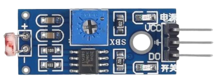
The Photoresistor Light Sensor (LDR LM393) is a versatile electronic component designed to detect light intensity. This sensor module includes a light-dependent resistor (LDR) that changes its resistance based on the ambient light levels. It operates within a voltage range of 3.3V to 5V and incorporates an LM393 comparator for signal processing, making it suitable for a variety of applications.
Explore Projects Built with Photoresistor Light Sensor 3Pin 3.3V-5V 5MM LDR LM393
Arduino UNO with LDR Sensor Light Detection System
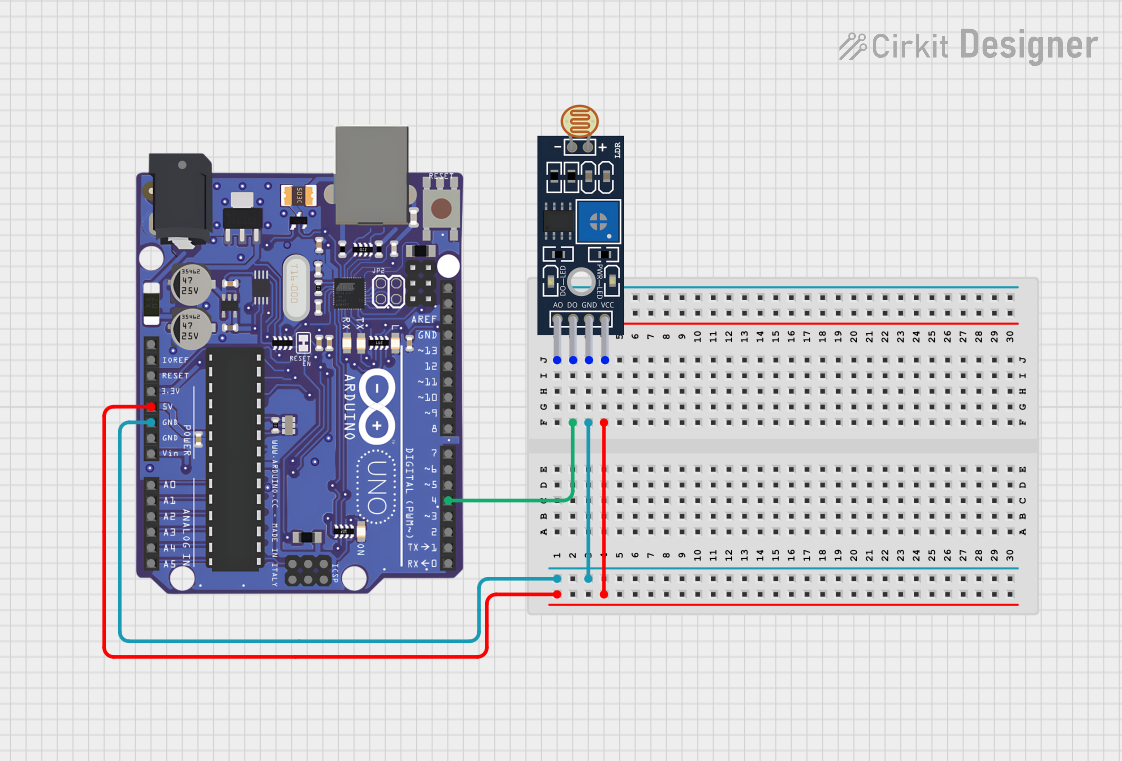
This circuit consists of an Arduino UNO microcontroller board connected to an LDR (Light Dependent Resistor) sensor module (LM393). The LDR sensor's digital output (D0) is connected to the Arduino's digital pin D4, allowing the Arduino to detect light intensity changes. The sensor is powered by the Arduino's 5V output, and both share a common ground.
Arduino UNO Based IR and LDR Sensor Array with LED Indicators
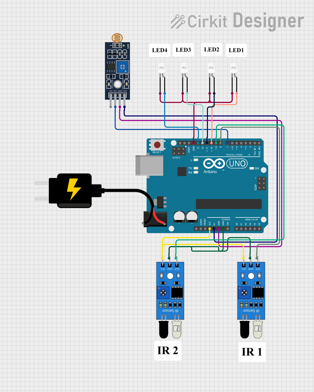
This circuit features an Arduino UNO microcontroller connected to two IR sensors and an LDR (light-dependent resistor) sensor module. The IR sensors are powered by the Arduino's 3.3V output, while the LDR sensor module is powered by the 5V output. Four LEDs are individually controlled by digital pins D10 to D13 on the Arduino, and the sensors' outputs are connected to digital pins D7 to D9, which can be used to trigger actions based on sensor inputs.
Raspberry Pi 3B Light Sensor Interface
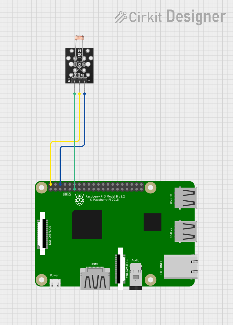
This circuit connects a KY-018 LDR Photo Resistor to a Raspberry Pi 3B for light sensing applications. The LDR's signal pin is connected to GPIO 11 on the Raspberry Pi, allowing the microcontroller to read the light levels detected by the sensor. The LDR is powered by the Raspberry Pi's 5V and ground pins.
Arduino-Controlled Light-Sensitive LED Circuit
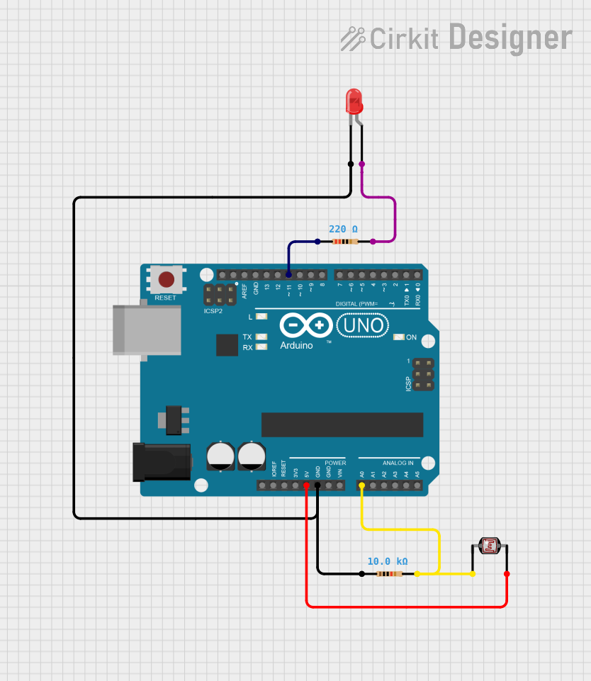
This circuit is designed to measure ambient light levels using a photocell (LDR) and adjust the brightness of an LED accordingly. The photocell and a 10kΩ resistor form a voltage divider connected to the Arduino's analog input A0, while the LED is driven by digital pin D11 through a 220Ω current-limiting resistor. The Arduino's firmware reads the light level, inverses the value to increase LED brightness as it gets darker, and outputs a corresponding PWM signal to control the LED intensity.
Explore Projects Built with Photoresistor Light Sensor 3Pin 3.3V-5V 5MM LDR LM393
Arduino UNO with LDR Sensor Light Detection System
This circuit consists of an Arduino UNO microcontroller board connected to an LDR (Light Dependent Resistor) sensor module (LM393). The LDR sensor's digital output (D0) is connected to the Arduino's digital pin D4, allowing the Arduino to detect light intensity changes. The sensor is powered by the Arduino's 5V output, and both share a common ground.
Arduino UNO Based IR and LDR Sensor Array with LED Indicators
This circuit features an Arduino UNO microcontroller connected to two IR sensors and an LDR (light-dependent resistor) sensor module. The IR sensors are powered by the Arduino's 3.3V output, while the LDR sensor module is powered by the 5V output. Four LEDs are individually controlled by digital pins D10 to D13 on the Arduino, and the sensors' outputs are connected to digital pins D7 to D9, which can be used to trigger actions based on sensor inputs.
Raspberry Pi 3B Light Sensor Interface
This circuit connects a KY-018 LDR Photo Resistor to a Raspberry Pi 3B for light sensing applications. The LDR's signal pin is connected to GPIO 11 on the Raspberry Pi, allowing the microcontroller to read the light levels detected by the sensor. The LDR is powered by the Raspberry Pi's 5V and ground pins.
Arduino-Controlled Light-Sensitive LED Circuit
This circuit is designed to measure ambient light levels using a photocell (LDR) and adjust the brightness of an LED accordingly. The photocell and a 10kΩ resistor form a voltage divider connected to the Arduino's analog input A0, while the LED is driven by digital pin D11 through a 220Ω current-limiting resistor. The Arduino's firmware reads the light level, inverses the value to increase LED brightness as it gets darker, and outputs a corresponding PWM signal to control the LED intensity.
Common Applications and Use Cases
- Automatic Lighting Systems: Turn lights on or off based on ambient light levels.
- Light Intensity Measurement: Measure and monitor light levels in various environments.
- Security Systems: Detect changes in light for security purposes.
- Robotics: Enable robots to respond to changes in light conditions.
- Consumer Electronics: Used in devices like automatic brightness control in screens.
Technical Specifications
Key Technical Details
| Parameter | Value |
|---|---|
| Operating Voltage | 3.3V - 5V |
| Comparator | LM393 |
| Light Sensor Type | Light-Dependent Resistor (LDR) |
| Output Type | Digital and Analog |
| Dimensions | 5mm LDR |
Pin Configuration and Descriptions
| Pin Number | Pin Name | Description |
|---|---|---|
| 1 | VCC | Power supply (3.3V - 5V) |
| 2 | GND | Ground |
| 3 | DO | Digital Output (High/Low based on light intensity) |
| 4 | AO | Analog Output (Variable voltage based on light intensity) |
Usage Instructions
How to Use the Component in a Circuit
- Power Supply: Connect the VCC pin to a 3.3V or 5V power supply and the GND pin to the ground.
- Digital Output: Connect the DO pin to a digital input pin on your microcontroller to read the high/low signal.
- Analog Output: Connect the AO pin to an analog input pin on your microcontroller to read the variable voltage signal.
Important Considerations and Best Practices
- Power Supply: Ensure the power supply voltage is within the specified range (3.3V to 5V).
- Light Sensitivity: The LDR's resistance changes with light intensity; ensure the sensor is placed in an appropriate location for accurate readings.
- Signal Processing: Use the LM393 comparator's digital output for simple high/low light detection or the analog output for more precise light intensity measurements.
Example Circuit with Arduino UNO
// Example code to read from the LDR LM393 sensor module
const int analogPin = A0; // Pin connected to AO (Analog Output)
const int digitalPin = 2; // Pin connected to DO (Digital Output)
int analogValue = 0;      // Variable to store the analog value
int digitalValue = 0;     // Variable to store the digital value

void setup() {
  Serial.begin(9600);      // Initialize serial communication
  pinMode(digitalPin, INPUT); // Set digital pin as input
}

void loop() {
  analogValue = analogRead(analogPin); // Read the analog value
  digitalValue = digitalRead(digitalPin); // Read the digital value

  // Print the values to the Serial Monitor
  Serial.print("Analog Value: ");
  Serial.print(analogValue);
  Serial.print(" | Digital Value: ");
  Serial.println(digitalValue);

  delay(1000); // Wait for 1 second before next reading
}
Troubleshooting and FAQs
Common Issues Users Might Face
No Output Signal:
- Solution: Check the power supply connections and ensure the sensor is receiving the correct voltage.
Inconsistent Readings:
- Solution: Ensure the sensor is not exposed to fluctuating light sources and is placed in a stable environment.
Digital Output Always High/Low:
- Solution: Adjust the sensitivity of the LM393 comparator using the onboard potentiometer (if available).
Solutions and Tips for Troubleshooting
- Verify Connections: Double-check all connections to ensure they are secure and correct.
- Check Power Supply: Ensure the power supply voltage is within the specified range (3.3V to 5V).
- Sensor Placement: Place the sensor in an appropriate location to avoid interference from unwanted light sources.
- Use Serial Monitor: Utilize the Serial Monitor in Arduino IDE to debug and monitor sensor readings.
By following this documentation, users can effectively integrate and utilize the Photoresistor Light Sensor (LDR LM393) in their projects, ensuring accurate light intensity detection and reliable performance.