How to Use plc haiwell at16s0r: Examples, Pinouts, and Specs
Introduction
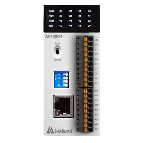
The Haiwell AT16S0R is a programmable logic controller (PLC) designed for industrial automation applications. It is equipped with 16 input channels and 16 relay output channels, making it suitable for controlling and monitoring a wide range of devices in industrial environments. The AT16S0R supports various communication protocols, ensuring seamless integration with other devices and systems. Known for its reliability, compact design, and ease of programming, this PLC is an excellent choice for both small-scale and large-scale automation projects.
Explore Projects Built with plc haiwell at16s0r


Explore Projects Built with plc haiwell at16s0r
Common Applications and Use Cases
- Industrial process automation
- Machine control and monitoring
- Building automation systems
- Conveyor belt systems
- Remote monitoring and control of equipment
- Integration with SCADA systems
Technical Specifications
Key Technical Details
| Specification | Value |
|---|---|
| Model | Haiwell AT16S0R |
| Input Channels | 16 (Digital Inputs) |
| Output Channels | 16 (Relay Outputs) |
| Input Voltage Range | DC 24V |
| Output Type | Relay (NO/NC contacts) |
| Communication Protocols | Modbus RTU, Modbus TCP, HaiwellBus |
| Power Supply Voltage | DC 24V |
| Power Consumption | ≤ 5W |
| Operating Temperature Range | -20°C to 60°C |
| Storage Temperature Range | -40°C to 70°C |
| Dimensions | 125mm x 90mm x 60mm |
| Mounting Type | DIN Rail |
Pin Configuration and Descriptions
Input Channels
| Pin Number | Description | Voltage Level |
|---|---|---|
| X0 - X15 | Digital Input Channels (X0-X15) | DC 24V |
Output Channels
| Pin Number | Description | Type |
|---|---|---|
| Y0 - Y15 | Relay Output Channels (Y0-Y15) | NO/NC Contacts |
Power and Communication
| Pin Number | Description | Notes |
|---|---|---|
| +24V, GND | Power Supply Input | DC 24V |
| RS485+/- | RS485 Communication Interface | Modbus RTU |
| Ethernet | Ethernet Port | Modbus TCP |
Usage Instructions
How to Use the Haiwell AT16S0R in a Circuit
- Power Connection: Connect a DC 24V power supply to the
+24VandGNDterminals. - Input Connections: Connect digital input devices (e.g., sensors, switches) to the input channels (X0-X15). Ensure the input voltage is within the specified range (DC 24V).
- Output Connections: Connect the devices to be controlled (e.g., motors, lights) to the relay output channels (Y0-Y15). Use the NO (Normally Open) or NC (Normally Closed) contacts as required.
- Communication Setup:
- For RS485 communication, connect the
RS485+andRS485-terminals to the corresponding terminals of the master device. - For Ethernet communication, connect the Ethernet port to your network or SCADA system.
- For RS485 communication, connect the
- Programming: Use the Haiwell programming software to create and upload your control logic. The software supports ladder logic, function block diagrams, and structured text programming.
Important Considerations and Best Practices
- Ensure the power supply voltage is stable and within the specified range (DC 24V).
- Use proper shielding and grounding for communication cables to minimize interference.
- Avoid exceeding the maximum current rating of the relay outputs to prevent damage.
- Regularly inspect and maintain the PLC to ensure reliable operation in industrial environments.
- Use surge protection devices to safeguard the PLC from voltage spikes.
Example: Connecting to an Arduino UNO
The Haiwell AT16S0R can communicate with an Arduino UNO via the RS485 interface. Below is an example of Arduino code to read data from the PLC using the Modbus RTU protocol.
#include <ModbusMaster.h>

// Instantiate ModbusMaster object
ModbusMaster node;

// Define RS485 communication pins
#define RE_DE 2  // Pin to control RS485 direction

void preTransmission() {
  digitalWrite(RE_DE, HIGH); // Enable transmission mode
}

void postTransmission() {
  digitalWrite(RE_DE, LOW);  // Enable reception mode
}

void setup() {
  // Initialize RS485 direction control pin
  pinMode(RE_DE, OUTPUT);
  digitalWrite(RE_DE, LOW);

  // Initialize serial communication
  Serial.begin(9600); // For debugging
  Serial1.begin(9600); // RS485 communication

  // Configure Modbus communication
  node.begin(1, Serial1); // Slave ID = 1
  node.preTransmission(preTransmission);
  node.postTransmission(postTransmission);
}

void loop() {
  uint8_t result;
  uint16_t data;

  // Read input status from PLC (e.g., X0-X15)
  result = node.readDiscreteInputs(0x0000, 16); // Read 16 inputs starting at address 0x0000

  if (result == node.ku8MBSuccess) {
    // Print the status of the first input (X0)
    data = node.getResponseBuffer(0);
    Serial.print("Input X0 status: ");
    Serial.println(bitRead(data, 0)); // Read bit 0 (X0)
  } else {
    Serial.println("Failed to read inputs from PLC.");
  }

  delay(1000); // Wait 1 second before the next read
}
Notes:
- Use an RS485-to-TTL converter to connect the Arduino UNO to the PLC.
- Ensure the slave ID and baud rate in the code match the PLC's configuration.
Troubleshooting and FAQs
Common Issues and Solutions
PLC Not Powering On
- Cause: Incorrect power supply voltage or loose connections.
- Solution: Verify the power supply voltage is DC 24V and check the wiring.
Inputs Not Detected
- Cause: Faulty input device or incorrect wiring.
- Solution: Test the input device and ensure it is properly connected to the input channels.
Outputs Not Activating
- Cause: Exceeding the relay's current rating or incorrect wiring.
- Solution: Verify the load current is within the relay's rating and check the wiring.
Communication Failure
- Cause: Incorrect communication settings or wiring issues.
- Solution: Ensure the baud rate, slave ID, and wiring match the PLC's configuration.
FAQs
Can the Haiwell AT16S0R be used with SCADA systems?
- Yes, it supports Modbus TCP and Modbus RTU protocols, making it compatible with most SCADA systems.
What is the maximum current rating for the relay outputs?
- The relay outputs can handle up to 5A at 250VAC or 30VDC.
Is the Haiwell programming software free?
- Yes, the Haiwell programming software is free to download from the manufacturer's website.
Can the PLC operate in extreme temperatures?
- Yes, it operates reliably within a temperature range of -20°C to 60°C.
Does the PLC support analog inputs/outputs?
- No, the AT16S0R model only supports digital inputs and relay outputs. For analog I/O, consider other Haiwell models.