How to Use ADUM150N1BRZ: Examples, Pinouts, and Specs
Introduction
The ADUM150N1BRZ is a digital isolator manufactured by Analog Devices. It provides galvanic isolation between two circuits, enabling safe data transfer while protecting sensitive low-voltage components from high-voltage surges. This component uses Analog Devices' iCoupler® technology, which ensures high-speed data transmission with low power consumption.
Explore Projects Built with ADUM150N1BRZ

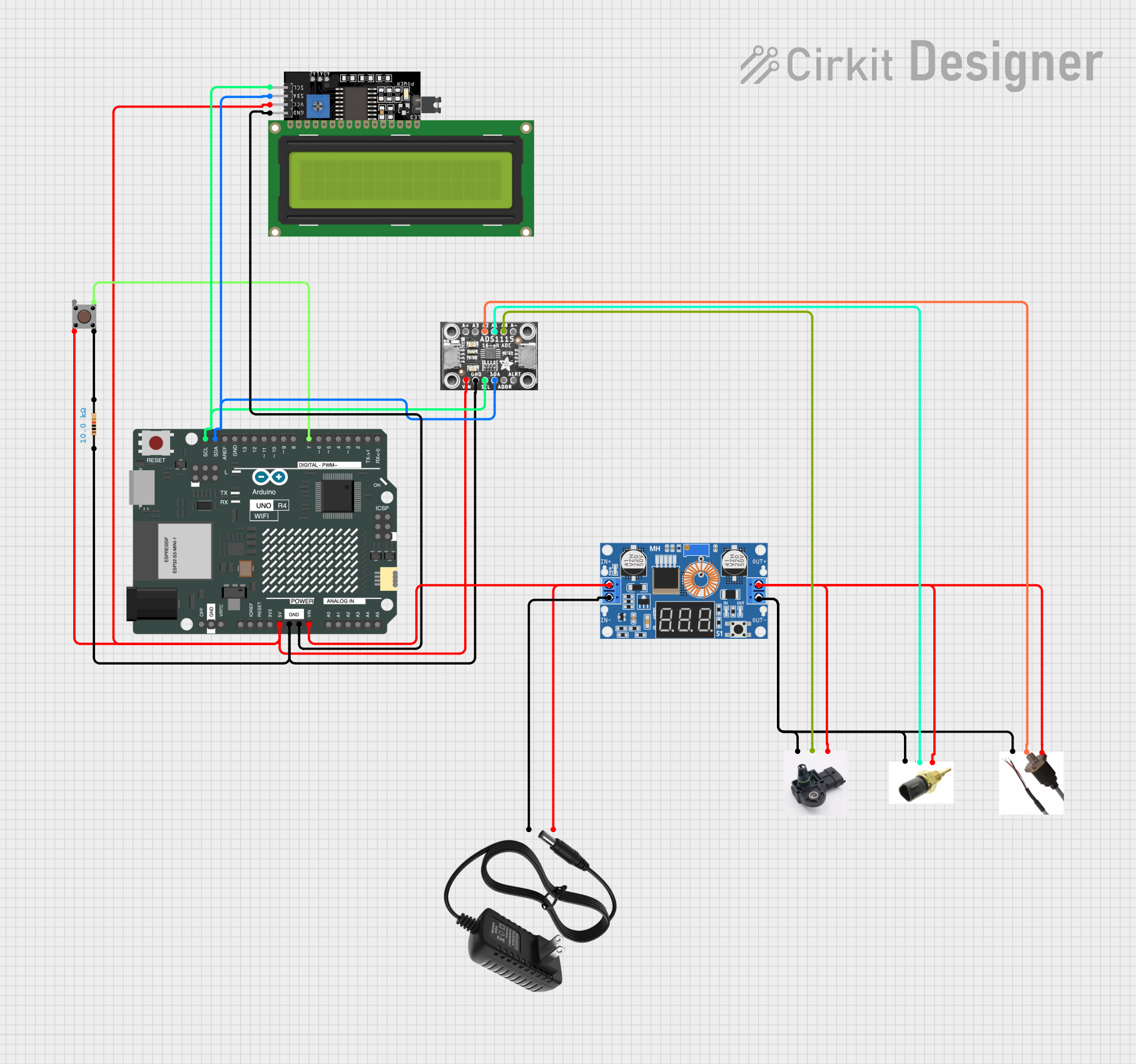
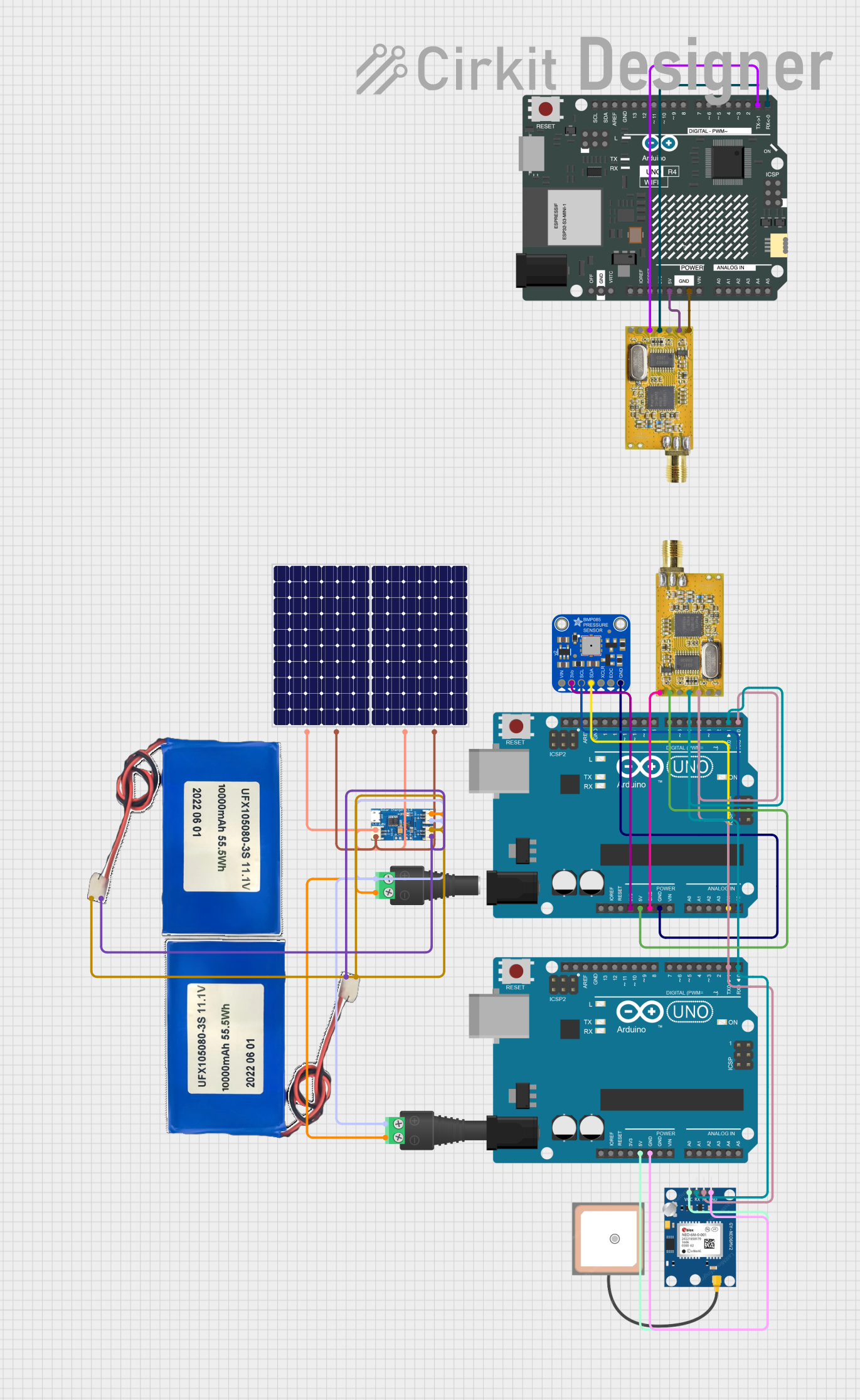
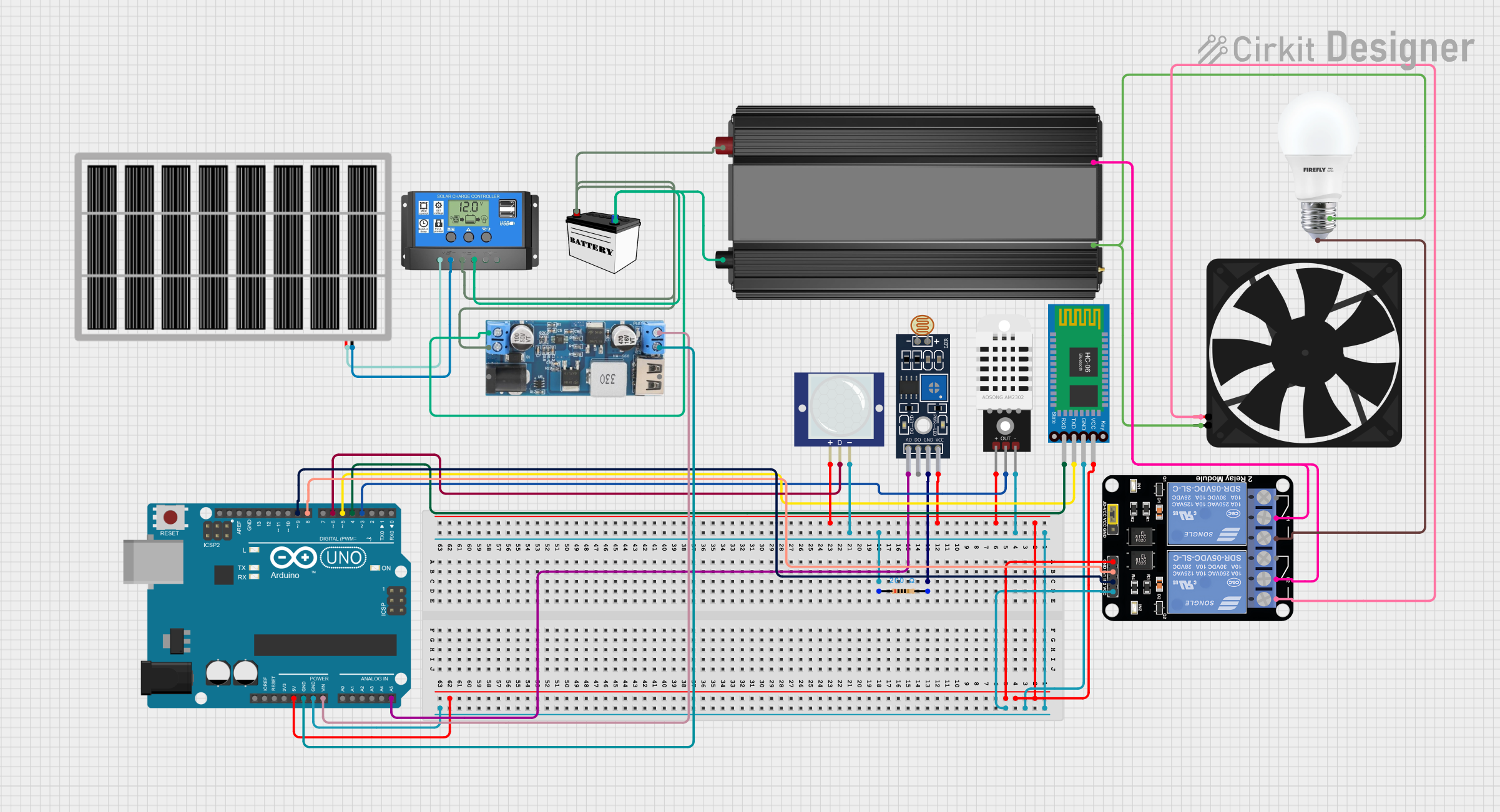
Explore Projects Built with ADUM150N1BRZ
Common Applications and Use Cases
- Industrial Automation: Isolating control systems from high-voltage machinery.
- Medical Devices: Ensuring patient safety by isolating sensitive electronics.
- Communication Systems: Protecting data lines in noisy or high-voltage environments.
- Power Supplies: Isolating feedback loops in switched-mode power supplies (SMPS).
Technical Specifications
The following table outlines the key technical details of the ADUM150N1BRZ:
| Parameter | Value |
|---|---|
| Isolation Voltage | 3 kV RMS |
| Data Rate | Up to 10 Mbps |
| Supply Voltage (VDD1, VDD2) | 3.0 V to 5.5 V |
| Propagation Delay | 50 ns (typical) |
| Power Consumption | 1.0 mA per channel (typical) |
| Operating Temperature Range | -40°C to +125°C |
| Package Type | 8-lead SOIC (Narrow Body) |
Pin Configuration and Descriptions
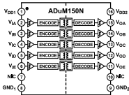
The ADUM150N1BRZ is an 8-pin device. The pin configuration and descriptions are as follows:
| Pin Number | Pin Name | Description |
|---|---|---|
| 1 | VDD1 | Supply voltage for side 1 (3.0 V to 5.5 V). |
| 2 | GND1 | Ground for side 1. |
| 3 | IN1 | Data input for side 1. |
| 4 | IN2 | Data input for side 1. |
| 5 | OUT2 | Data output for side 2. |
| 6 | OUT1 | Data output for side 2. |
| 7 | GND2 | Ground for side 2. |
| 8 | VDD2 | Supply voltage for side 2 (3.0 V to 5.5 V). |
Usage Instructions
How to Use the ADUM150N1BRZ in a Circuit
- Power Supply: Connect VDD1 and VDD2 to separate power supplies (3.0 V to 5.5 V). Ensure that GND1 and GND2 are isolated from each other to maintain galvanic isolation.
- Data Input/Output: Connect the data signals to the IN1 and IN2 pins on the input side. The corresponding outputs will appear on OUT1 and OUT2 on the isolated side.
- Bypass Capacitors: Place decoupling capacitors (e.g., 0.1 µF) close to the VDD1 and VDD2 pins to reduce noise and ensure stable operation.
- PCB Layout: Maintain sufficient spacing between the high-voltage and low-voltage sides to prevent arcing or breakdown.
Important Considerations and Best Practices
- Isolation Voltage: Do not exceed the rated isolation voltage of 3 kV RMS.
- Data Rate: Ensure that the data rate does not exceed 10 Mbps for reliable operation.
- Thermal Management: Operate the device within the specified temperature range (-40°C to +125°C) to avoid thermal damage.
- Signal Integrity: Use short and direct traces for data lines to minimize signal degradation.
Example: Connecting the ADUM150N1BRZ to an Arduino UNO
The ADUM150N1BRZ can be used to isolate an Arduino UNO from a high-voltage circuit. Below is an example of how to connect and program the device:
Circuit Connections
- Connect VDD1 to the Arduino's 5V pin and GND1 to the Arduino's GND pin.
- Connect IN1 to a digital output pin on the Arduino (e.g., D2).
- Connect VDD2 to the high-voltage circuit's power supply and GND2 to its ground.
- OUT1 will output the isolated signal to the high-voltage circuit.
Arduino Code Example
// Example code to send a digital signal through the ADUM150N1BRZ
const int signalPin = 2; // Pin connected to IN1 of ADUM150N1BRZ

void setup() {
  pinMode(signalPin, OUTPUT); // Set the signal pin as an output
}

void loop() {
  digitalWrite(signalPin, HIGH); // Send a HIGH signal
  delay(1000); // Wait for 1 second
  digitalWrite(signalPin, LOW);  // Send a LOW signal
  delay(1000); // Wait for 1 second
}
Troubleshooting and FAQs
Common Issues and Solutions
No Output Signal on OUT1/OUT2:
- Cause: Missing or incorrect power supply connections.
- Solution: Verify that VDD1 and VDD2 are powered correctly and that GND1 and GND2 are isolated.
Signal Distortion or Noise:
- Cause: Poor PCB layout or missing decoupling capacitors.
- Solution: Add 0.1 µF decoupling capacitors close to VDD1 and VDD2. Ensure short and direct traces for data lines.
Device Overheating:
- Cause: Operating outside the specified voltage or temperature range.
- Solution: Check the supply voltage and ambient temperature. Ensure they are within the specified limits.
Isolation Breakdown:
- Cause: Exceeding the rated isolation voltage.
- Solution: Ensure that the voltage difference between GND1 and GND2 does not exceed 3 kV RMS.
FAQs
Q1: Can the ADUM150N1BRZ be used for bidirectional communication?
A1: No, the ADUM150N1BRZ is designed for unidirectional data transfer. For bidirectional communication, consider using other isolators from Analog Devices that support bidirectional operation.
Q2: What is the maximum distance between the isolated sides?
A2: The maximum distance is determined by the PCB layout and the isolation voltage rating. Ensure sufficient spacing to maintain isolation integrity.
Q3: Can I use the ADUM150N1BRZ with a 3.3 V system?
A3: Yes, the ADUM150N1BRZ supports supply voltages from 3.0 V to 5.5 V, making it compatible with 3.3 V systems.