How to Use LM75: Examples, Pinouts, and Specs
Introduction
The LM75 is a precision integrated-circuit temperature sensor that offers an easy-to-use I2C interface to provide temperature readings with a high degree of accuracy. It is widely used in system thermal management, environmental monitoring, and personal electronics to measure temperature with minimal interfacing and component count.
Explore Projects Built with LM75


Explore Projects Built with LM75
Common Applications and Use Cases
- System thermal management for computers and servers
- Environmental monitoring in smart home systems
- Over-temperature protection in electronic circuits
- Industrial temperature control systems
- Personal electronics, such as wearables and smartphones
Technical Specifications
Key Technical Details
- Supply Voltage (Vcc): 2.7V to 5.5V
- Temperature Range: -55°C to +125°C
- Accuracy: ±2°C from -25°C to 100°C
- Resolution: 0.125°C
- Interface: I2C serial bus
- Addressing: 7-bit slave address with selectable MSB bits (A2, A1, A0)
- Operating Current: 1mA (typical)
- Shutdown Current: 4µA (typical)
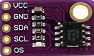
Pin Configuration and Descriptions
| Pin Number | Name | Description |
|---|---|---|
| 1 | SDA | Serial Data Line for I2C communication |
| 2 | SCL | Serial Clock Line for I2C communication |
| 3 | A2 | Address pin 2, selectable bit |
| 4 | A1 | Address pin 1, selectable bit |
| 5 | A0 | Address pin 0, selectable bit |
| 6 | GND | Ground reference for the power supply |
| 7 | OS | Overtemperature Shutdown output |
| 8 | Vcc | Supply voltage |
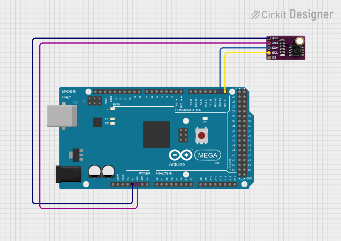
Usage Instructions
How to Use the LM75 in a Circuit
- Power Supply: Connect the Vcc pin to a 2.7V to 5.5V power supply and the GND pin to the ground.
- I2C Communication: Connect the SDA and SCL pins to the I2C data and clock lines, respectively. Ensure pull-up resistors are in place as required for the I2C bus.
- Address Selection: Set the A2, A1, and A0 pins to either high (Vcc) or low (GND) to determine the device's I2C address.
- Overtemperature Shutdown (OS): The OS pin can be left unconnected if not used, or connected to a microcontroller's interrupt input to signal when the temperature exceeds a programmed limit.
Important Considerations and Best Practices
- Ensure that the LM75 is not subjected to temperatures beyond its operating range.
- Avoid running the I2C bus lines near noisy signals to prevent communication errors.
- Use proper decoupling capacitors close to the Vcc and GND pins to minimize power supply noise.
- When using multiple LM75 sensors on the same I2C bus, ensure each device has a unique address by setting the A2, A1, and A0 pins accordingly.
Example Code for Arduino UNO
#include <Wire.h>

// LM75 I2C address (depends on A2, A1, A0 pin status)
const int LM75_Address = 0x48;

void setup() {
  Wire.begin(); // Initialize I2C
  Serial.begin(9600); // Start serial communication at 9600 baud
}

void loop() {
  Wire.beginTransmission(LM75_Address); // Start communication with LM75
  Wire.write(0x00); // Select temperature register
  Wire.endTransmission();
  Wire.requestFrom(LM75_Address, 2); // Request 2 bytes from the temperature register

  if(Wire.available() == 2) {
    int tempRaw = Wire.read() << 8 | Wire.read(); // Read the two bytes
    float temperature = tempRaw / 256.0; // Convert to temperature
    Serial.print("Temperature: ");
    Serial.print(temperature);
    Serial.println(" C");
  }

  delay(1000); // Wait for 1 second before reading again
}
Troubleshooting and FAQs
Common Issues Users Might Face
- Inaccurate Temperature Readings: Ensure that the LM75 is not exposed to external heat sources and that the I2C bus is free from noise.
- No Communication with Sensor: Check the wiring, ensure pull-up resistors are installed on the I2C lines, and verify that the correct I2C address is being used.
Solutions and Tips for Troubleshooting
- Check Connections: Verify that all connections are secure and correct.
- I2C Address: Use an I2C scanner sketch to confirm the LM75's address on the bus.
- Pull-up Resistors: Ensure that appropriate pull-up resistors are in place for the SDA and SCL lines.
- Power Supply: Confirm that the power supply is within the specified range and is stable.
FAQs
Q: Can I use multiple LM75 sensors on the same I2C bus? A: Yes, you can set different addresses for each LM75 by configuring the A2, A1, and A0 pins.
Q: What is the purpose of the OS pin? A: The OS pin is an overtemperature shutdown output that can be used to signal a microcontroller or other circuitry when the temperature exceeds a programmed threshold.
Q: How do I set the high and low temperature limits? A: You can program the high and low temperature limits by writing to the respective registers in the LM75 via the I2C interface. Refer to the LM75 datasheet for detailed register descriptions and programming instructions.