
How to Use Inductors: Examples, Pinouts, and Specs
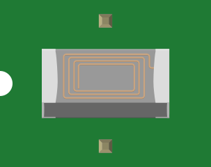
 Design with Inductors in Cirkit Designer
Introduction
Inductors are passive electrical components that store energy in a magnetic field when electric current flows through them. They are typically made of a coil of wire wound around a core, which can be air, ferrite, or another magnetic material. Inductors are widely used in electronic circuits for their ability to resist changes in current and to filter or store energy.
Explore Projects Built with Inductors
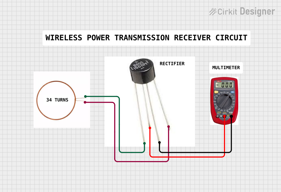 Open Project in Cirkit Designer
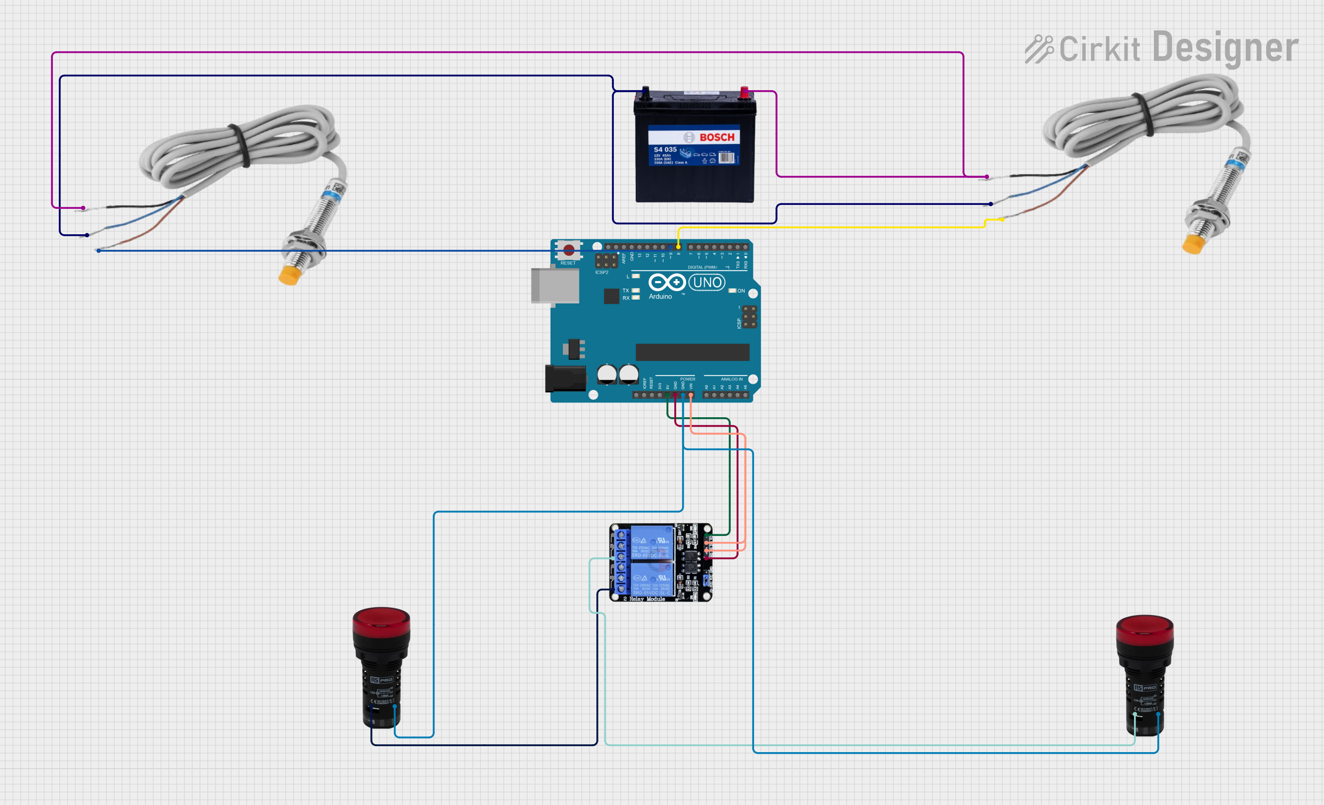 Open Project in Cirkit Designer
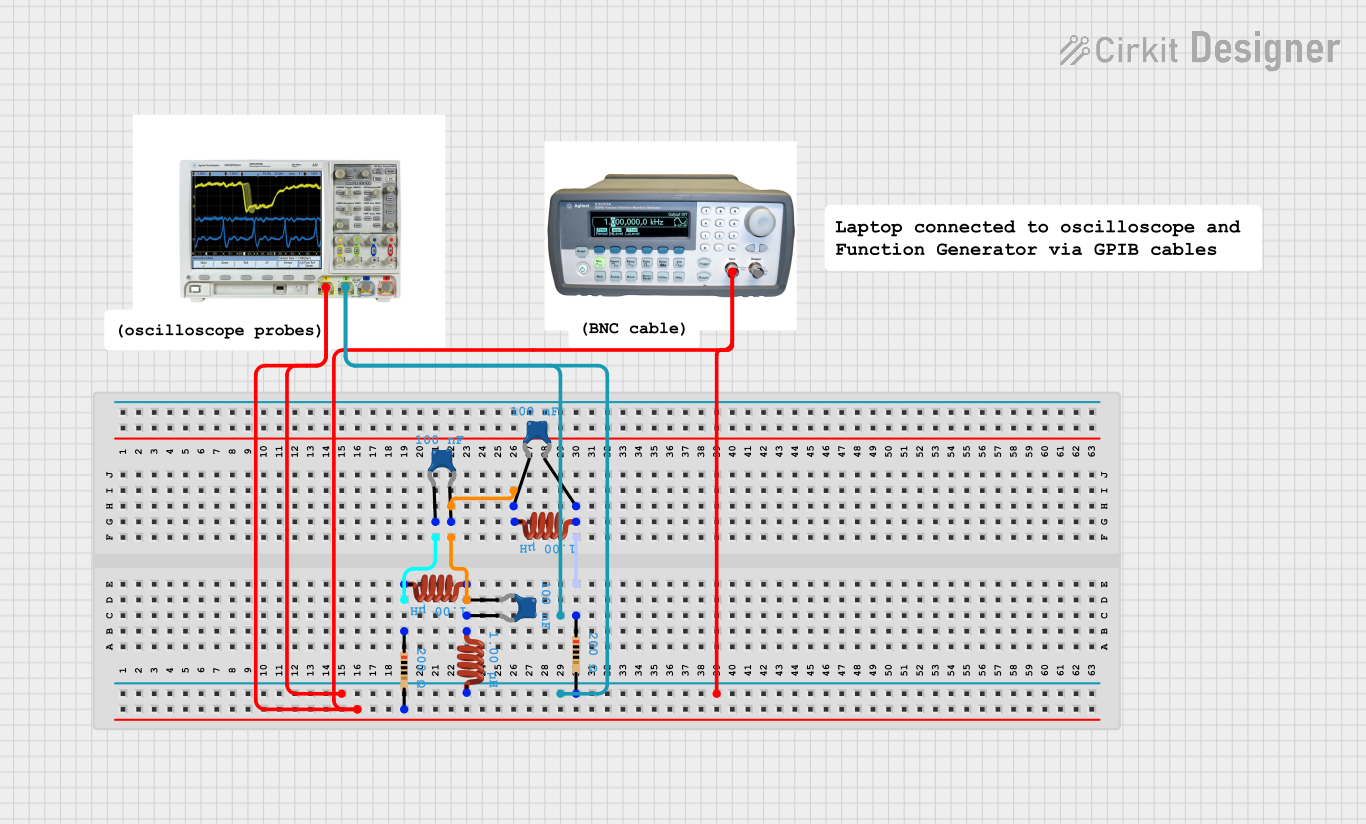 Open Project in Cirkit Designer
 Open Project in Cirkit Designer
Explore Projects Built with Inductors
Open Project in Cirkit DesignerOpen Project in Cirkit DesignerOpen Project in Cirkit DesignerOpen Project in Cirkit DesignerCommon Applications and Use Cases
- Filtering: Used in power supplies and audio circuits to filter out unwanted noise or ripple.
- Energy Storage: Found in DC-DC converters and other power electronics to store energy temporarily.
- Tuning Circuits: Used in radio frequency (RF) circuits to select specific frequencies.
- Transformers: Inductors are a key component in transformers for voltage conversion.
- Chokes: Used to block high-frequency AC signals while allowing DC or low-frequency signals to pass.
Technical Specifications
Inductors come in various shapes, sizes, and specifications depending on their intended application. Below are the key technical parameters and a typical pin configuration.
Key Technical Details
| Parameter | Description |
|---|---|
| Inductance (L) | Measured in henries (H), typically in microhenries (µH) or millihenries (mH). |
| Current Rating | Maximum current the inductor can handle without overheating or saturating. |
| Saturation Current | The current at which the core material saturates, reducing inductance. |
| DC Resistance (DCR) | The resistance of the wire used in the inductor, measured in ohms (Ω). |
| Quality Factor (Q) | Ratio of inductive reactance to resistance, indicating efficiency. |
| Self-Resonant Frequency | Frequency at which the inductor's inductance and parasitic capacitance resonate. |
| Core Material | Material used for the core, such as air, ferrite, or iron. |
Pin Configuration and Descriptions
Inductors are typically two-terminal components. Below is a table describing the pins:
| Pin Number | Description |
|---|---|
| 1 | Input terminal for current flow. |
| 2 | Output terminal for current flow. |
Note: Some inductors, such as those used in transformers, may have multiple windings and additional pins.
Usage Instructions
How to Use Inductors in a Circuit
- Determine the Required Inductance: Calculate the inductance value needed for your application using circuit design equations.
- Select an Appropriate Inductor: Choose an inductor with the correct inductance, current rating, and core material.
- Connect the Inductor:
- For filtering applications, connect the inductor in series with the load or in parallel with a capacitor.
- For energy storage, use the inductor in conjunction with a switching device (e.g., MOSFET) and a capacitor.
- Observe Polarity (if applicable): While most inductors are non-polarized, some specialized inductors (e.g., coupled inductors) may have polarity markings.
- Avoid Saturation: Ensure the current through the inductor does not exceed its saturation current rating.
Important Considerations and Best Practices
- Core Material: Choose the core material based on the operating frequency. Ferrite cores are ideal for high-frequency applications, while iron cores are better for low-frequency circuits.
- Parasitic Effects: Be aware of parasitic capacitance and resistance, which can affect performance at high frequencies.
- Thermal Management: Ensure adequate cooling to prevent overheating, especially in high-current applications.
- Placement in PCB Design: Place inductors away from sensitive components to minimize electromagnetic interference (EMI).
Example: Using an Inductor with Arduino UNO
Below is an example of using an inductor in a simple LC filter circuit to smooth a PWM signal from an Arduino UNO.
/*
  Example: Using an LC filter to smooth a PWM signal from Arduino UNO.
  This code generates a PWM signal on pin 9, which is filtered using an
  inductor and capacitor to produce a smoother DC output.
*/

const int pwmPin = 9; // PWM output pin

void setup() {
  pinMode(pwmPin, OUTPUT); // Set pin 9 as output
}

void loop() {
  // Generate a PWM signal with 50% duty cycle
  analogWrite(pwmPin, 128); // 128 corresponds to 50% duty cycle
  delay(1000); // Wait for 1 second
}
Circuit Setup:
- Connect the Arduino's PWM pin (pin 9) to one terminal of the inductor.
- Connect the other terminal of the inductor to the positive terminal of a capacitor.
- Connect the negative terminal of the capacitor to ground.
- The output voltage can be measured across the capacitor.
Troubleshooting and FAQs
Common Issues and Solutions
Inductor Overheating:
- Cause: Exceeding the current rating or poor thermal management.
- Solution: Use an inductor with a higher current rating or improve cooling.
Low Efficiency:
- Cause: High DC resistance (DCR) or poor quality factor (Q).
- Solution: Select an inductor with lower DCR and higher Q.
Noise in Circuit:
- Cause: Electromagnetic interference (EMI) from the inductor.
- Solution: Use shielded inductors or place the inductor away from sensitive components.
Saturation of Core:
- Cause: Current exceeds the saturation current rating.
- Solution: Use an inductor with a higher saturation current rating.
FAQs
Q1: Can I use any inductor for high-frequency applications?
A1: No, you need to select an inductor with a core material suitable for high frequencies, such as ferrite.
Q2: How do I calculate the required inductance for a filter?
A2: Use the formula ( L = \frac{1}{(2\pi f)^2 C} ), where ( f ) is the cutoff frequency and ( C ) is the capacitance.
Q3: What happens if I reverse the connections of an inductor?
A3: Most inductors are non-polarized, so reversing the connections will not affect their operation. However, for coupled inductors or transformers, polarity matters.
Q4: Can inductors be used to store energy like capacitors?
A4: Yes, inductors store energy in their magnetic field, but they release it differently compared to capacitors. Inductors resist changes in current, while capacitors resist changes in voltage.