
How to Use OV7725: Examples, Pinouts, and Specs
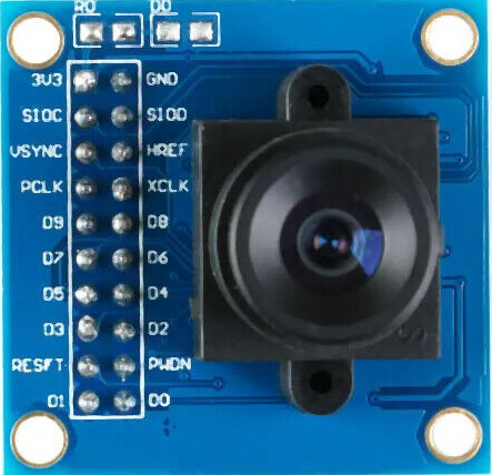
 Design with OV7725 in Cirkit Designer
Introduction
The OV7725 is a low-voltage CMOS image sensor manufactured by OmniVision. It is designed for high-quality video and image capture, offering VGA resolution (640x480) at high frame rates. The sensor supports multiple output formats, including YUV, RGB, and RAW, making it versatile for a wide range of applications. Its compact design and low power consumption make it ideal for use in security cameras, robotics, mobile devices, and other embedded systems requiring real-time image processing.
Explore Projects Built with OV7725
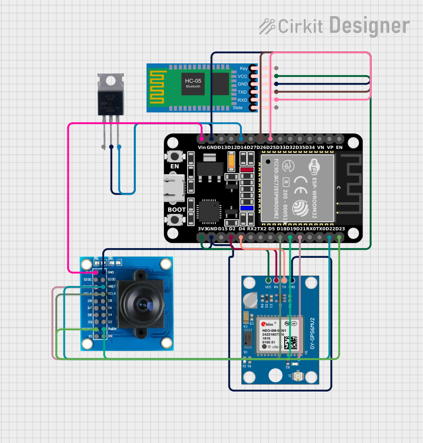 Open Project in Cirkit Designer
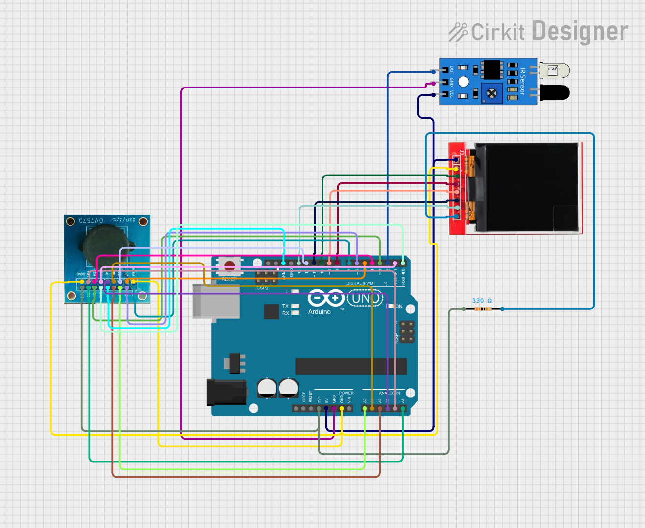 Open Project in Cirkit Designer
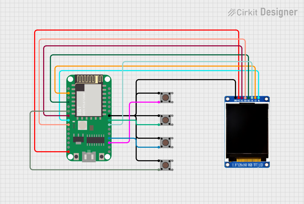 Open Project in Cirkit Designer
 Open Project in Cirkit Designer
Explore Projects Built with OV7725
Open Project in Cirkit DesignerOpen Project in Cirkit DesignerOpen Project in Cirkit DesignerOpen Project in Cirkit DesignerCommon Applications
- Security and surveillance cameras
- Robotics and machine vision
- Mobile devices and wearable cameras
- Industrial automation
- Gesture recognition systems
Technical Specifications
Key Technical Details
| Parameter | Specification |
|---|---|
| Resolution | VGA (640x480) |
| Pixel Size | 6.0 µm x 6.0 µm |
| Frame Rate | Up to 60 fps (at VGA resolution) |
| Output Formats | YUV, RGB, RAW |
| Supply Voltage | 2.5V (analog), 1.8V (digital core) |
| Operating Temperature | -30°C to +70°C |
| Power Consumption | Low power consumption |
| Interface | SCCB (Serial Camera Control Bus) |
| Shutter Type | Rolling shutter |
Pin Configuration and Descriptions
The OV7725 comes in a 24-pin package. Below is the pin configuration:
| Pin Number | Pin Name | Description |
|---|---|---|
| 1 | VDD_IO | I/O power supply (1.8V or 2.8V) |
| 2 | GND | Ground |
| 3 | PCLK | Pixel clock output |
| 4 | VSYNC | Vertical synchronization signal |
| 5 | HREF | Horizontal reference signal |
| 6 | D0 | Data output bit 0 |
| 7 | D1 | Data output bit 1 |
| 8 | D2 | Data output bit 2 |
| 9 | D3 | Data output bit 3 |
| 10 | D4 | Data output bit 4 |
| 11 | D5 | Data output bit 5 |
| 12 | D6 | Data output bit 6 |
| 13 | D7 | Data output bit 7 |
| 14 | RESETB | Active-low reset input |
| 15 | PWDN | Power down mode input |
| 16 | SCL | SCCB clock input |
| 17 | SDA | SCCB data input/output |
| 18 | VDD | Core power supply (1.8V) |
| 19 | GND | Ground |
| 20 | MCLK | Master clock input |
| 21 | NC | Not connected |
| 22 | NC | Not connected |
| 23 | NC | Not connected |
| 24 | NC | Not connected |
Usage Instructions
How to Use the OV7725 in a Circuit
- Power Supply: Connect the OV7725 to a 2.5V analog power supply and a 1.8V digital core power supply. Ensure proper decoupling capacitors are used to minimize noise.
- Clock Input: Provide a stable master clock (MCLK) signal to the MCLK pin. A typical frequency is 24 MHz.
- SCCB Interface: Use the SCCB interface (pins SCL and SDA) to configure the sensor's registers. This allows you to set parameters such as resolution, frame rate, and output format.
- Data Output: Connect the data output pins (D0-D7) to a microcontroller or processor capable of handling the desired output format (e.g., YUV or RGB).
- Synchronization Signals: Use the VSYNC and HREF signals for frame and line synchronization.
- Reset and Power Down: Use the RESETB pin to reset the sensor and the PWDN pin to enable or disable power-down mode.
Important Considerations
- Voltage Levels: Ensure that the I/O voltage levels are compatible with the connected microcontroller or processor.
- Clock Stability: A stable clock signal is critical for proper operation.
- Lens Selection: Use a compatible lens with the appropriate focal length and aperture for your application.
- Heat Management: Ensure adequate ventilation or heat dissipation if the sensor operates in high-temperature environments.
Example: Connecting OV7725 to Arduino UNO
Below is an example of how to interface the OV7725 with an Arduino UNO for basic image capture:
#include <Wire.h> // Include the Wire library for SCCB communication

#define OV7725_SCCB_ADDR 0x42 // OV7725 SCCB address

void setup() {
  Wire.begin(); // Initialize I2C communication
  Serial.begin(9600); // Initialize serial communication for debugging

  // Reset the OV7725
  Wire.beginTransmission(OV7725_SCCB_ADDR);
  Wire.write(0x12); // Register address for COM7 (common control register)
  Wire.write(0x80); // Reset command
  Wire.endTransmission();
  delay(100); // Wait for the sensor to reset

  // Configure the OV7725 for VGA resolution
  Wire.beginTransmission(OV7725_SCCB_ADDR);
  Wire.write(0x12); // Register address for COM7
  Wire.write(0x00); // Set VGA resolution
  Wire.endTransmission();

  Serial.println("OV7725 initialized.");
}

void loop() {
  // Add code to capture and process image data
  Serial.println("Capturing image...");
  delay(1000); // Simulate image capture delay
}
Notes:
- The above code initializes the OV7725 and sets it to VGA resolution. Additional configuration may be required depending on your application.
- Use a logic level shifter if the Arduino operates at 5V logic levels, as the OV7725 operates at 1.8V or 2.8V.
Troubleshooting and FAQs
Common Issues
No Image Output:
- Ensure the MCLK signal is stable and within the required frequency range.
- Verify that the SCCB interface is correctly configured and the sensor registers are properly initialized.
- Check the power supply connections and voltage levels.
Distorted or Noisy Image:
- Verify that the lens is clean and properly focused.
- Ensure proper grounding and minimize electrical noise in the circuit.
Sensor Not Responding to SCCB Commands:
- Check the SCCB address and ensure it matches the OV7725's default address (0x42).
- Verify the pull-up resistors on the SCL and SDA lines.
FAQs
Q: Can the OV7725 capture images in low light?
A: Yes, the OV7725 has good low-light performance, but additional lighting may be required for very dark environments.
Q: What is the maximum frame rate supported by the OV7725?
A: The OV7725 supports up to 60 frames per second at VGA resolution.
Q: Can the OV7725 output RAW image data?
A: Yes, the OV7725 supports RAW output format in addition to YUV and RGB.
Q: Is the OV7725 compatible with 5V systems?
A: The OV7725 operates at 1.8V or 2.8V. Use a logic level shifter to interface with 5V systems.
Q: How do I focus the OV7725?
A: The OV7725 requires a compatible lens with adjustable focus. Rotate the lens to achieve the desired focus.
This concludes the documentation for the OV7725 CMOS image sensor.