Cirkit Designer Logo
Cirkit Designer
Your all-in-one circuit design IDE
Home / 
Component Documentation

How to Use KY-005: Examples, Pinouts, and Specs

Image of KY-005
Cirkit Designer LogoDesign with KY-005 in Cirkit Designer

Introduction

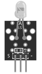
The KY-005 is a digital temperature sensor module that utilizes the DS18B20 sensor to provide accurate and reliable temperature readings. This module is widely used in electronic projects for temperature monitoring and control due to its ease of use and compatibility with microcontrollers like Arduino. The KY-005 supports a wide temperature range and features a digital output, making it suitable for applications such as weather stations, HVAC systems, and industrial temperature monitoring.

Explore Projects Built with KY-005

Use Cirkit Designer to design, explore, and prototype these projects online. Some projects support real-time simulation. Click "Open Project" to start designing instantly!
Arduino Nano-Based Wireless Joystick and Motion Controller
Image of hand gesture: A project utilizing KY-005 in a practical application
This circuit features an Arduino Nano microcontroller interfaced with an HC-05 Bluetooth module, an MPU-6050 accelerometer/gyroscope, and a KY-023 Dual Axis Joystick Module. The Arduino Nano is powered by a 9V battery through a rocker switch and communicates with the HC-05 for Bluetooth connectivity, reads joystick positions from the KY-023 module via analog inputs, and communicates with the MPU-6050 over I2C to capture motion data. The circuit is likely designed for wireless control and motion sensing applications, such as a remote-controlled robot or a game controller.
Cirkit Designer LogoOpen Project in Cirkit Designer
Arduino Nano Joystick-Controlled Bluetooth Module with Battery Power
Image of padelpro transmitter: A project utilizing KY-005 in a practical application
This circuit is a wireless joystick controller that uses an Arduino Nano to read analog signals from a KY-023 Dual Axis Joystick Module and transmits the data via an HC-05 Bluetooth Module. The system is powered by a 18650 Li-Ion battery with a rocker switch for power control.
Cirkit Designer LogoOpen Project in Cirkit Designer
ESP32-Based Security System with RFID and Laser Tripwire
Image of CPE doorlock system: A project utilizing KY-005 in a practical application
This circuit is designed for a comprehensive security and access control system with motion detection, access via RFID, and a break-beam sensor. It includes a solenoid lock controlled by a relay, visual and audible alerts, and a robust power management system with solar and battery backup to ensure uninterrupted operation.
Cirkit Designer LogoOpen Project in Cirkit Designer
Arduino Mega 2560 Bluetooth-Controlled Flame Detection System with Servo Actuation
Image of apv circuit 1: A project utilizing KY-005 in a practical application
This circuit uses an Arduino Mega 2560 to monitor four KY-026 flame sensors and control four micro servo motors. The HC-05 Bluetooth module allows for wireless communication, enabling remote monitoring and control of the system.
Cirkit Designer LogoOpen Project in Cirkit Designer

Explore Projects Built with KY-005

Use Cirkit Designer to design, explore, and prototype these projects online. Some projects support real-time simulation. Click "Open Project" to start designing instantly!
Image of hand gesture: A project utilizing KY-005 in a practical application
Arduino Nano-Based Wireless Joystick and Motion Controller
This circuit features an Arduino Nano microcontroller interfaced with an HC-05 Bluetooth module, an MPU-6050 accelerometer/gyroscope, and a KY-023 Dual Axis Joystick Module. The Arduino Nano is powered by a 9V battery through a rocker switch and communicates with the HC-05 for Bluetooth connectivity, reads joystick positions from the KY-023 module via analog inputs, and communicates with the MPU-6050 over I2C to capture motion data. The circuit is likely designed for wireless control and motion sensing applications, such as a remote-controlled robot or a game controller.
Cirkit Designer LogoOpen Project in Cirkit Designer
Image of padelpro transmitter: A project utilizing KY-005 in a practical application
Arduino Nano Joystick-Controlled Bluetooth Module with Battery Power
This circuit is a wireless joystick controller that uses an Arduino Nano to read analog signals from a KY-023 Dual Axis Joystick Module and transmits the data via an HC-05 Bluetooth Module. The system is powered by a 18650 Li-Ion battery with a rocker switch for power control.
Cirkit Designer LogoOpen Project in Cirkit Designer
Image of CPE doorlock system: A project utilizing KY-005 in a practical application
ESP32-Based Security System with RFID and Laser Tripwire
This circuit is designed for a comprehensive security and access control system with motion detection, access via RFID, and a break-beam sensor. It includes a solenoid lock controlled by a relay, visual and audible alerts, and a robust power management system with solar and battery backup to ensure uninterrupted operation.
Cirkit Designer LogoOpen Project in Cirkit Designer
Image of apv circuit 1: A project utilizing KY-005 in a practical application
Arduino Mega 2560 Bluetooth-Controlled Flame Detection System with Servo Actuation
This circuit uses an Arduino Mega 2560 to monitor four KY-026 flame sensors and control four micro servo motors. The HC-05 Bluetooth module allows for wireless communication, enabling remote monitoring and control of the system.
Cirkit Designer LogoOpen Project in Cirkit Designer

Technical Specifications

  • Sensor Type: DS18B20 Digital Temperature Sensor
  • Temperature Range: -55°C to +125°C (-67°F to +257°F)
  • Accuracy: ±0.5°C (in the range of -10°C to +85°C)
  • Operating Voltage: 3.0V to 5.5V
  • Output Type: Digital (1-Wire protocol)
  • Power Consumption: Low power consumption
  • Dimensions: Compact module design for easy integration

Pin Configuration and Descriptions

The KY-005 module has three pins, as described in the table below:

Pin Number Pin Name Description
1 GND Ground pin, connects to the ground of the circuit
2 VCC Power supply pin, connects to 3.3V or 5V
3 DOUT Digital output pin, communicates temperature data

Usage Instructions

How to Use the KY-005 in a Circuit

  1. Wiring the KY-005:

    • Connect the GND pin of the KY-005 to the ground (GND) of your microcontroller.
    • Connect the VCC pin to a 3.3V or 5V power supply, depending on your microcontroller's voltage level.
    • Connect the DOUT pin to a digital input pin on your microcontroller.
  2. Pull-Up Resistor:

    • The DS18B20 sensor requires a pull-up resistor (typically 4.7kΩ) between the DOUT pin and the VCC pin to ensure proper communication.
  3. Programming:

    • Use a microcontroller like Arduino to read temperature data from the KY-005. The module communicates using the 1-Wire protocol, which requires a compatible library.

Arduino Example Code

Below is an example of how to use the KY-005 with an Arduino UNO:

#include <OneWire.h>
#include <DallasTemperature.h>

// Define the pin connected to the KY-005 DOUT pin
#define ONE_WIRE_BUS 2

// Initialize the OneWire and DallasTemperature libraries
OneWire oneWire(ONE_WIRE_BUS);
DallasTemperature sensors(&oneWire);

void setup() {
  Serial.begin(9600); // Start serial communication at 9600 baud
  sensors.begin();    // Initialize the DS18B20 sensor
  Serial.println("KY-005 Temperature Sensor Initialized");
}

void loop() {
  sensors.requestTemperatures(); // Request temperature data from the sensor
  float temperature = sensors.getTempCByIndex(0); // Get temperature in Celsius
  
  // Check if the temperature reading is valid
  if (temperature != DEVICE_DISCONNECTED_C) {
    Serial.print("Temperature: ");
    Serial.print(temperature);
    Serial.println(" °C");
  } else {
    Serial.println("Error: Sensor not detected!");
  }
  
  delay(1000); // Wait 1 second before the next reading
}

Important Considerations and Best Practices

  • Ensure the pull-up resistor is properly connected to the DOUT pin for stable communication.
  • Avoid exposing the sensor to temperatures beyond its specified range (-55°C to +125°C).
  • Use proper insulation if the sensor is deployed in a humid or wet environment.
  • If multiple DS18B20 sensors are used on the same 1-Wire bus, each sensor must have a unique address.

Troubleshooting and FAQs

Common Issues and Solutions

  1. No Temperature Reading:

    • Cause: The pull-up resistor is missing or incorrectly connected.
    • Solution: Verify the pull-up resistor (4.7kΩ) is connected between the DOUT and VCC pins.
  2. Incorrect Temperature Values:

    • Cause: Poor wiring or loose connections.
    • Solution: Check all connections and ensure the sensor is properly powered.
  3. Sensor Not Detected:

    • Cause: The sensor is not properly connected or is damaged.
    • Solution: Verify the wiring and replace the sensor if necessary.
  4. Interference on the 1-Wire Bus:

    • Cause: Long wires or noisy environments.
    • Solution: Use shorter wires and shielded cables to reduce interference.

FAQs

  • Q: Can the KY-005 be powered with 3.3V?

    • A: Yes, the KY-005 can operate with a power supply of 3.0V to 5.5V.
  • Q: How many sensors can I connect to a single 1-Wire bus?

    • A: You can connect multiple DS18B20 sensors to the same 1-Wire bus, but each sensor must have a unique address.
  • Q: Is the KY-005 suitable for outdoor use?

    • A: The sensor itself is not waterproof. If used outdoors, ensure it is properly insulated or use a waterproof version of the DS18B20.
  • Q: What is the maximum cable length for the 1-Wire bus?

    • A: The maximum cable length depends on the environment and power supply, but typically it is recommended to keep it under 30 meters for reliable communication.

This concludes the documentation for the KY-005 module.