Cirkit Designer Logo
Cirkit Designer
Your all-in-one circuit design IDE
Home / 
Component Documentation

How to Use Power Supply: Examples, Pinouts, and Specs

Image of Power Supply
Cirkit Designer LogoDesign with Power Supply in Cirkit Designer

Introduction

The DROK 12V to 5V Buck Converter is a compact and efficient power supply module designed to step down a 12V DC input to a stable 5V DC output. This device is ideal for powering low-voltage electronic components and systems, ensuring reliable and consistent performance. Its small size and high efficiency make it suitable for a wide range of applications.

Explore Projects Built with Power Supply

Use Cirkit Designer to design, explore, and prototype these projects online. Some projects support real-time simulation. Click "Open Project" to start designing instantly!
AC to DC Power Supply with Transformer and Bridge Rectifier
Image of BRIDGE RECTIFIER: A project utilizing Power Supply in a practical application
This circuit is a basic AC to DC power supply that steps down 220V AC to a lower voltage using a transformer, rectifies it to DC using a bridge rectifier made of diodes, and smooths the output with an electrolytic capacitor. A rocker switch is used to turn the power supply on and off.
Cirkit Designer LogoOpen Project in Cirkit Designer
USB-Powered DC Gear Motor with LED Indicator
Image of Hand Crank mobile charger : A project utilizing Power Supply in a practical application
This circuit appears to be a power supply unit with a bridge rectifier connected to a DC gear motor, indicating it is designed to convert AC to DC power for the motor. An electrolytic capacitor is used for smoothing the DC output, and a 7805 voltage regulator is included to provide a stable 5V output. Additionally, there is an LED with a series resistor, likely serving as a power indicator light.
Cirkit Designer LogoOpen Project in Cirkit Designer
Dual 5V Power Supply Distribution Circuit with Toggle Switch Control
Image of rfdriver: A project utilizing Power Supply in a practical application
This circuit consists of two 5V 5A power supplies connected to an AC wall plug point, providing DC output through a 12-way connector. The ground connections from both power supplies are interconnected and also connected to the ground pins of two toggle switches. The DC outputs from the power supplies are separately connected to different pins on the 12-way connector, with each power supply output being switchable via one of the toggle switches.
Cirkit Designer LogoOpen Project in Cirkit Designer
AC to DC Power Supply with Voltage Regulation and Overcurrent Protection
Image of PENGATUR VOLTAN: A project utilizing Power Supply in a practical application
This circuit appears to be a power supply unit with a transformer for stepping down voltage, a bridge rectifier for converting AC to DC, and a voltage regulator for stabilizing the output voltage. It includes a Zener diode for overvoltage protection, capacitors for smoothing out ripples in the DC supply, and a fuse for overcurrent protection. A toggle switch and a rocker switch are used to control the power flow, and there is an LED indicator connected through resistors, likely for power-on indication.
Cirkit Designer LogoOpen Project in Cirkit Designer

Explore Projects Built with Power Supply

Use Cirkit Designer to design, explore, and prototype these projects online. Some projects support real-time simulation. Click "Open Project" to start designing instantly!
Image of BRIDGE RECTIFIER: A project utilizing Power Supply in a practical application
AC to DC Power Supply with Transformer and Bridge Rectifier
This circuit is a basic AC to DC power supply that steps down 220V AC to a lower voltage using a transformer, rectifies it to DC using a bridge rectifier made of diodes, and smooths the output with an electrolytic capacitor. A rocker switch is used to turn the power supply on and off.
Cirkit Designer LogoOpen Project in Cirkit Designer
Image of Hand Crank mobile charger : A project utilizing Power Supply in a practical application
USB-Powered DC Gear Motor with LED Indicator
This circuit appears to be a power supply unit with a bridge rectifier connected to a DC gear motor, indicating it is designed to convert AC to DC power for the motor. An electrolytic capacitor is used for smoothing the DC output, and a 7805 voltage regulator is included to provide a stable 5V output. Additionally, there is an LED with a series resistor, likely serving as a power indicator light.
Cirkit Designer LogoOpen Project in Cirkit Designer
Image of rfdriver: A project utilizing Power Supply in a practical application
Dual 5V Power Supply Distribution Circuit with Toggle Switch Control
This circuit consists of two 5V 5A power supplies connected to an AC wall plug point, providing DC output through a 12-way connector. The ground connections from both power supplies are interconnected and also connected to the ground pins of two toggle switches. The DC outputs from the power supplies are separately connected to different pins on the 12-way connector, with each power supply output being switchable via one of the toggle switches.
Cirkit Designer LogoOpen Project in Cirkit Designer
Image of PENGATUR VOLTAN: A project utilizing Power Supply in a practical application
AC to DC Power Supply with Voltage Regulation and Overcurrent Protection
This circuit appears to be a power supply unit with a transformer for stepping down voltage, a bridge rectifier for converting AC to DC, and a voltage regulator for stabilizing the output voltage. It includes a Zener diode for overvoltage protection, capacitors for smoothing out ripples in the DC supply, and a fuse for overcurrent protection. A toggle switch and a rocker switch are used to control the power flow, and there is an LED indicator connected through resistors, likely for power-on indication.
Cirkit Designer LogoOpen Project in Cirkit Designer

Common Applications and Use Cases

  • Powering microcontrollers (e.g., Arduino, Raspberry Pi)
  • Supplying power to sensors, modules, and other low-voltage devices
  • Automotive electronics for converting 12V car battery voltage to 5V
  • DIY electronics projects and prototyping
  • Portable power systems

Technical Specifications

The following table outlines the key technical details of the DROK 12V to 5V Buck Converter:

Parameter Value
Input Voltage Range 8V to 22V DC
Output Voltage 5V DC (fixed)
Output Current Up to 3A
Efficiency Up to 96%
Operating Temperature -40°C to +85°C
Dimensions 22mm x 17mm x 4mm
Weight 5 grams

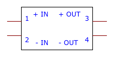
Pin Configuration and Descriptions

The DROK 12V to 5V Buck Converter has four pins for input and output connections. The table below describes each pin:

Pin Name Description
VIN+ Positive input voltage (8V to 22V DC)
VIN- Negative input voltage (ground)
VOUT+ Positive output voltage (5V DC)
VOUT- Negative output voltage (ground)

Usage Instructions

How to Use the Component in a Circuit

  1. Connect the Input Voltage:

    • Attach the positive terminal of your DC power source (e.g., 12V battery) to the VIN+ pin.
    • Connect the negative terminal of the power source to the VIN- pin.
  2. Connect the Output Voltage:

    • Connect the VOUT+ pin to the positive terminal of the device or circuit you want to power.
    • Connect the VOUT- pin to the ground of the device or circuit.
  3. Verify Connections:

    • Double-check all connections to ensure proper polarity and avoid short circuits.
  4. Power On:

    • Turn on the power source. The module will step down the input voltage to a stable 5V output.

Important Considerations and Best Practices

  • Input Voltage Range: Ensure the input voltage is within the specified range (8V to 22V DC). Exceeding this range may damage the module.
  • Heat Dissipation: Although the module is highly efficient, it may generate heat under high current loads. Ensure proper ventilation or use a heatsink if necessary.
  • Load Current: Do not exceed the maximum output current of 3A to prevent overheating or damage.
  • Polarity: Always connect the input and output pins with the correct polarity to avoid damaging the module.

Example: Using with an Arduino UNO

The DROK 12V to 5V Buck Converter can be used to power an Arduino UNO from a 12V power source. Below is an example circuit and code:

Circuit Connections

  • Connect the VIN+ pin of the buck converter to the positive terminal of a 12V DC power source.
  • Connect the VIN- pin to the ground of the power source.
  • Connect the VOUT+ pin to the 5V pin of the Arduino UNO.
  • Connect the VOUT- pin to the GND pin of the Arduino UNO.

Example Code

// Example code for Arduino UNO powered by DROK 12V to 5V Buck Converter
// This code blinks an LED connected to pin 13

void setup() {
  pinMode(13, OUTPUT); // Set pin 13 as an output
}

void loop() {
  digitalWrite(13, HIGH); // Turn the LED on
  delay(1000);            // Wait for 1 second
  digitalWrite(13, LOW);  // Turn the LED off
  delay(1000);            // Wait for 1 second
}

Troubleshooting and FAQs

Common Issues and Solutions

  1. No Output Voltage:

    • Cause: Incorrect input connections or insufficient input voltage.
    • Solution: Verify that the input voltage is within the 8V to 22V range and that the connections are correct.
  2. Overheating:

    • Cause: Excessive load current or poor ventilation.
    • Solution: Reduce the load current to below 3A and ensure proper airflow around the module.
  3. Output Voltage Fluctuations:

    • Cause: Unstable input voltage or excessive load.
    • Solution: Use a stable DC power source and ensure the load does not exceed the module's capacity.
  4. Module Not Working After Connection:

    • Cause: Reverse polarity or input voltage exceeding the maximum limit.
    • Solution: Check and correct the polarity of the connections. Replace the module if it has been damaged.

FAQs

Q1: Can this module be used with a 24V input?
A1: No, the maximum input voltage is 22V. Using a 24V input may damage the module.

Q2: Is the output voltage adjustable?
A2: No, the output voltage is fixed at 5V.

Q3: Can I use this module to power a Raspberry Pi?
A3: Yes, the module can provide a stable 5V output suitable for powering a Raspberry Pi. Ensure the current requirement does not exceed 3A.

Q4: Does the module have built-in overcurrent protection?
A4: No, the module does not have built-in overcurrent protection. Avoid exceeding the maximum current rating to prevent damage.