How to Use Darlington Driver: Examples, Pinouts, and Specs
Introduction
A Darlington Driver is an electronic component that consists of a pair of bipolar junction transistors (BJTs) connected in such a way that the current amplified by the first transistor is further amplified by the second one. This configuration allows for a high current gain, making it ideal for driving high-power devices like motors, solenoids, and relays. Darlington Drivers are commonly used in applications where a low-power signal needs to control a high-power load.
Explore Projects Built with Darlington Driver
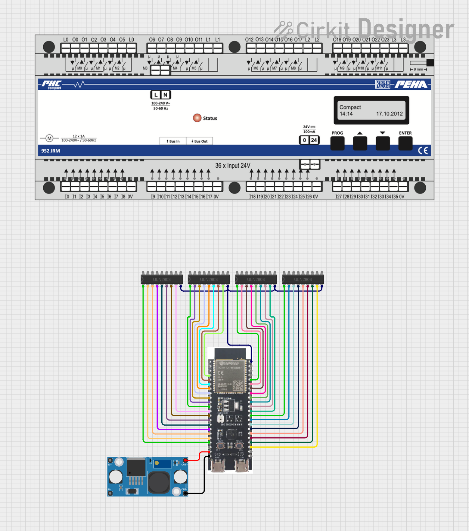
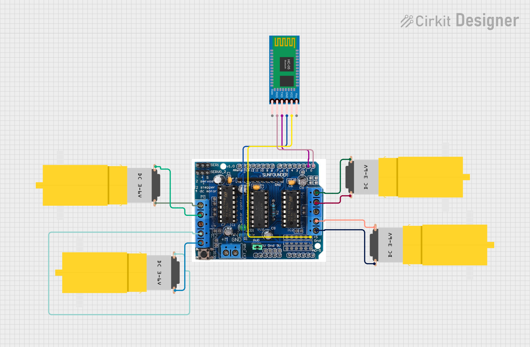
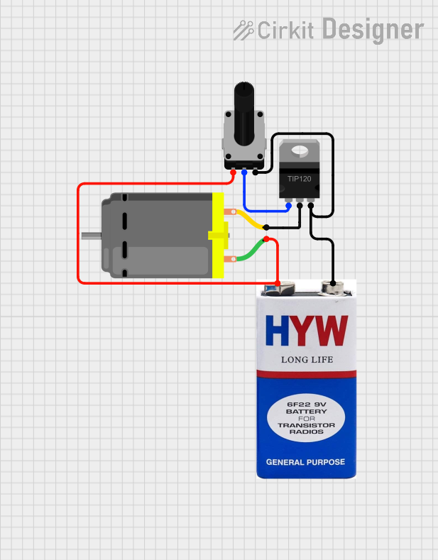
Explore Projects Built with Darlington Driver
Technical Specifications
Key Technical Details
- Voltage Rating: The maximum collector-emitter voltage the Darlington Driver can handle.
- Current Rating: The maximum collector current that can flow through the device.
- Power Dissipation: The maximum power the device can dissipate without damage.
- Gain: The current amplification factor, typically very high for Darlington pairs.
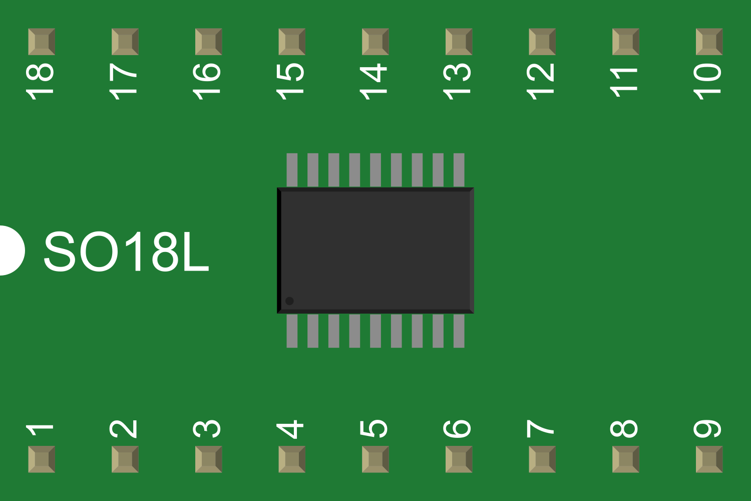
Pin Configuration and Descriptions
| Pin Number | Name | Description |
|---|---|---|
| 1 | Base (B1) | Input signal to the first transistor. |
| 2 | Collector (C1) | Connected to the collector of the first transistor. Often tied to the second collector (C2). |
| 3 | Emitter (E1) | Emitter of the first transistor, connected to the base of the second transistor (B2). |
| 4 | Collector (C2) | Output collector, connected to the load. |
| 5 | Emitter (E2) | Emitter of the second transistor; this is the output emitter. |
Usage Instructions
How to Use the Darlington Driver in a Circuit
- Connecting the Load: Connect the high-power load to the collector (C2) and the emitter (E2) of the Darlington Driver.
- Input Signal: Apply a low-power input signal to the base (B1) of the first transistor.
- Base Resistor: Include a resistor between the input signal and the base (B1) to limit the base current.
- Power Supply: Ensure that the power supply voltage is within the voltage rating of the Darlington Driver and that it can provide sufficient current for the load.
Important Considerations and Best Practices
- Heat Dissipation: Darlington Drivers can generate significant heat when driving large loads. Use a heatsink if necessary.
- Protection Diodes: When driving inductive loads like motors or solenoids, use a flyback diode to protect the Darlington Driver from voltage spikes.
- Input Signal: The input signal voltage should be sufficient to turn on the first transistor fully.
Troubleshooting and FAQs
Common Issues
- Driver Overheating: This can occur if the power dissipation exceeds the device's rating. Check the load current and ensure proper heat sinking.
- Insufficient Drive Current: Ensure that the input signal can provide enough base current to fully saturate the transistors.
Solutions and Tips for Troubleshooting
- Check Connections: Verify that all connections are secure and that the component is not damaged.
- Measure Voltages: Use a multimeter to check the voltages at the pins to ensure they are within the expected range.
FAQs
Q: Can I drive the Darlington Driver directly from a microcontroller? A: Yes, but ensure that the microcontroller can supply enough current to the base and that a base resistor is used to limit the current.
Q: What is the purpose of the flyback diode? A: The flyback diode protects the Darlington Driver from high-voltage spikes that occur when the inductive load is switched off.
Example Code for Arduino UNO
// Define the pin connected to the Darlington Driver base
const int darlingtonPin = 2;

void setup() {
  // Set the Darlington Driver pin as an output
  pinMode(darlingtonPin, OUTPUT);
}

void loop() {
  // Turn on the high-power load
  digitalWrite(darlingtonPin, HIGH);
  delay(1000); // Wait for 1 second

  // Turn off the high-power load
  digitalWrite(darlingtonPin, LOW);
  delay(1000); // Wait for 1 second
}
Note: When using the Darlington Driver with an Arduino, ensure that the current requirements of the load do not exceed the Arduino's maximum current rating for the digital pins. If the load requires more current, use an external power supply and ensure that the grounds are connected.