Cirkit Designer Logo
Cirkit Designer
Your all-in-one circuit design IDE
Home / 
Component Documentation

How to Use ST-Link v2: Examples, Pinouts, and Specs

Image of ST-Link v2
Cirkit Designer LogoDesign with ST-Link v2 in Cirkit Designer

Introduction

The ST-Link v2 is a versatile programming and debugging tool designed for STM32 microcontrollers. It provides a seamless interface for developers to upload firmware, debug applications, and monitor real-time performance via a USB connection. Compact and easy to use, the ST-Link v2 is an essential tool for embedded systems development.

Explore Projects Built with ST-Link v2

Use Cirkit Designer to design, explore, and prototype these projects online. Some projects support real-time simulation. Click "Open Project" to start designing instantly!
STM32F103C8T6-Based Spectral Sensor with ST7735S Display and Pushbutton Control
Image of ColorSensor: A project utilizing ST-Link v2 in a practical application
This circuit features an STM32F103C8T6 microcontroller interfaced with a China ST7735S 160x128 display and two spectral sensors (Adafruit AS7262 and AS7261). It also includes two pushbuttons for user input, with the microcontroller managing the display and sensor data processing.
Cirkit Designer LogoOpen Project in Cirkit Designer
STM32F103C8T6-Based Water Level Monitoring and Communication System with SIM900A and LoRa Connectivity
Image of water level: A project utilizing ST-Link v2 in a practical application
This circuit features a microcontroller (STM32F103C8T6) interfaced with a SIM900A GSM module, an HC-SR04 ultrasonic sensor, a water level sensor, and a LoRa Ra-02 SX1278 module for long-range communication. The STM32F103C8T6 is configured to communicate with the GSM module and LoRa module via serial connections, and it reads data from the ultrasonic and water level sensors. An FTDI Programmer is connected for programming and serial communication with the microcontroller.
Cirkit Designer LogoOpen Project in Cirkit Designer
STM32 Nucleo F303RE Controlled Ultrasonic Sensing with RGB Feedback and I2C LCD Display
Image of CS435-final: A project utilizing ST-Link v2 in a practical application
This circuit features a STM32 Nucleo F303RE microcontroller interfaced with three HC-SR04 ultrasonic sensors for distance measurement and a 20x4 LCD display over I2C for data output. Additionally, there is a WS2812 RGB LED strip controlled by the microcontroller for visual feedback. The power supply provides a common 5V to the LCD, ultrasonic sensors, LED strip, and the microcontroller's +5V input, with all components sharing a common ground.
Cirkit Designer LogoOpen Project in Cirkit Designer
ESP32 and Logic Level Converter-Based Wi-Fi Controlled Interface
Image of Toshiba AC ESP32 devkit v1: A project utilizing ST-Link v2 in a practical application
This circuit features an ESP32 Devkit V1 microcontroller connected to a Bi-Directional Logic Level Converter, which facilitates voltage level shifting between the ESP32 and external components. The ESP32 is powered through its VIN pin via an alligator clip cable, and the logic level converter is connected to various pins on the ESP32 to manage different voltage levels for communication.
Cirkit Designer LogoOpen Project in Cirkit Designer

Explore Projects Built with ST-Link v2

Use Cirkit Designer to design, explore, and prototype these projects online. Some projects support real-time simulation. Click "Open Project" to start designing instantly!
Image of ColorSensor: A project utilizing ST-Link v2 in a practical application
STM32F103C8T6-Based Spectral Sensor with ST7735S Display and Pushbutton Control
This circuit features an STM32F103C8T6 microcontroller interfaced with a China ST7735S 160x128 display and two spectral sensors (Adafruit AS7262 and AS7261). It also includes two pushbuttons for user input, with the microcontroller managing the display and sensor data processing.
Cirkit Designer LogoOpen Project in Cirkit Designer
Image of water level: A project utilizing ST-Link v2 in a practical application
STM32F103C8T6-Based Water Level Monitoring and Communication System with SIM900A and LoRa Connectivity
This circuit features a microcontroller (STM32F103C8T6) interfaced with a SIM900A GSM module, an HC-SR04 ultrasonic sensor, a water level sensor, and a LoRa Ra-02 SX1278 module for long-range communication. The STM32F103C8T6 is configured to communicate with the GSM module and LoRa module via serial connections, and it reads data from the ultrasonic and water level sensors. An FTDI Programmer is connected for programming and serial communication with the microcontroller.
Cirkit Designer LogoOpen Project in Cirkit Designer
Image of CS435-final: A project utilizing ST-Link v2 in a practical application
STM32 Nucleo F303RE Controlled Ultrasonic Sensing with RGB Feedback and I2C LCD Display
This circuit features a STM32 Nucleo F303RE microcontroller interfaced with three HC-SR04 ultrasonic sensors for distance measurement and a 20x4 LCD display over I2C for data output. Additionally, there is a WS2812 RGB LED strip controlled by the microcontroller for visual feedback. The power supply provides a common 5V to the LCD, ultrasonic sensors, LED strip, and the microcontroller's +5V input, with all components sharing a common ground.
Cirkit Designer LogoOpen Project in Cirkit Designer
Image of Toshiba AC ESP32 devkit v1: A project utilizing ST-Link v2 in a practical application
ESP32 and Logic Level Converter-Based Wi-Fi Controlled Interface
This circuit features an ESP32 Devkit V1 microcontroller connected to a Bi-Directional Logic Level Converter, which facilitates voltage level shifting between the ESP32 and external components. The ESP32 is powered through its VIN pin via an alligator clip cable, and the logic level converter is connected to various pins on the ESP32 to manage different voltage levels for communication.
Cirkit Designer LogoOpen Project in Cirkit Designer

Common Applications and Use Cases

  • Programming STM32 microcontrollers with custom firmware.
  • Debugging embedded applications using breakpoints and step-through execution.
  • Real-time monitoring of variables and system performance.
  • Flashing bootloaders or firmware updates in production environments.
  • Educational purposes for learning STM32 development.

Technical Specifications

Key Technical Details

  • Supported Microcontrollers: STM32 ARM Cortex-M series.
  • Interface: USB 2.0 (Type-A to Mini-B or Micro-B, depending on the model).
  • Programming Protocols: SWD (Serial Wire Debug) and JTAG.
  • Voltage Levels: Supports target voltages from 1.65V to 3.6V.
  • Operating System Compatibility: Windows, macOS, Linux (with appropriate drivers).
  • Software Support: STM32CubeIDE, Keil uVision, IAR Embedded Workbench, OpenOCD.

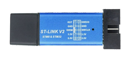
Pin Configuration and Descriptions

The ST-Link v2 typically uses a 4-pin or 6-pin header for connecting to the target microcontroller. Below is the pinout for the 4-pin SWD interface:

Pin Name Description
1 VCC Target voltage reference (1.65V–3.6V).
2 SWDIO Serial Wire Debug Input/Output.
3 GND Ground connection.
4 SWCLK Serial Wire Debug Clock.

For the 6-pin JTAG interface, the additional pins are:

Pin Name Description
5 TDI JTAG Test Data Input.
6 TDO JTAG Test Data Output.

Usage Instructions

How to Use the ST-Link v2 in a Circuit

  1. Connect the ST-Link v2 to the Target Microcontroller:

    • Use the SWD or JTAG interface to connect the ST-Link v2 to the STM32 microcontroller.
    • Ensure the VCC pin matches the target microcontroller's voltage level.
  2. Install Required Software:

    • Download and install STM32CubeIDE or another compatible IDE.
    • Install the ST-Link USB driver (available on the STMicroelectronics website).
  3. Power the Target Device:

    • Ensure the target microcontroller is powered either externally or via the VCC pin of the ST-Link v2.
  4. Program the Microcontroller:

    • Open the IDE and configure the ST-Link v2 as the debugger/programmer.
    • Load the firmware or project into the IDE and click "Program" or "Debug".
  5. Debugging:

    • Set breakpoints, watch variables, and step through the code using the IDE's debugging tools.

Important Considerations and Best Practices

  • Always verify the target microcontroller's voltage level before connecting the ST-Link v2.
  • Use short, high-quality cables to minimize signal interference.
  • Avoid powering the target device solely through the ST-Link v2 if it requires high current.
  • Ensure the ST-Link v2 firmware is up to date for compatibility with the latest STM32 devices.

Example: Using ST-Link v2 with Arduino IDE

The ST-Link v2 can also be used to program STM32 microcontrollers via the Arduino IDE. Below is an example of uploading a simple "Blink" program to an STM32 board:

// Example: Blink an LED on an STM32 board using Arduino IDE
// Ensure the ST-Link v2 is connected to the STM32 board via SWD interface.

void setup() {
  pinMode(LED_BUILTIN, OUTPUT); // Set the built-in LED pin as output
}

void loop() {
  digitalWrite(LED_BUILTIN, HIGH); // Turn the LED on
  delay(1000);                     // Wait for 1 second
  digitalWrite(LED_BUILTIN, LOW);  // Turn the LED off
  delay(1000);                     // Wait for 1 second
}

To upload this code:

  1. Install the STM32 board package in the Arduino IDE.
  2. Select the appropriate STM32 board and "ST-Link" as the upload method.
  3. Click "Upload" to program the microcontroller.

Troubleshooting and FAQs

Common Issues and Solutions

  1. ST-Link v2 Not Detected by the IDE:

    • Ensure the ST-Link USB driver is installed correctly.
    • Check the USB cable and port for proper connection.
    • Update the ST-Link firmware using the ST-Link Utility.
  2. Programming Fails or Debugger Disconnects:

    • Verify the SWD or JTAG connections are secure and correctly oriented.
    • Check the target microcontroller's power supply.
    • Ensure the correct target voltage is selected.
  3. Target Microcontroller Not Responding:

    • Confirm the microcontroller is not in a low-power or reset state.
    • Check for any hardware issues, such as damaged pins or incorrect wiring.
  4. Firmware Update Required:

    • Use the ST-Link Utility to update the firmware to the latest version.

FAQs

Q: Can the ST-Link v2 power the target microcontroller?
A: The ST-Link v2 can provide a reference voltage (VCC) but is not designed to power the target device. Use an external power source for the microcontroller.

Q: Is the ST-Link v2 compatible with non-STM32 microcontrollers?
A: The ST-Link v2 is primarily designed for STM32 devices. However, it may work with other ARM Cortex-M microcontrollers using OpenOCD.

Q: How do I update the ST-Link v2 firmware?
A: Download the ST-Link Utility from the STMicroelectronics website, connect the ST-Link v2, and follow the on-screen instructions to update the firmware.

Q: Can I use the ST-Link v2 with Linux?
A: Yes, the ST-Link v2 is compatible with Linux. Install OpenOCD or other compatible tools to use it on Linux systems.