Cirkit Designer Logo
Cirkit Designer
Your all-in-one circuit design IDE
Home / 
Component Documentation

How to Use KY-012: Examples, Pinouts, and Specs

Image of KY-012
Cirkit Designer LogoDesign with KY-012 in Cirkit Designer

Introduction

The KY-012 is a passive piezoelectric buzzer module that produces sound when an AC signal is applied. Unlike active buzzers, which generate sound on their own, passive buzzers require an external signal to produce sound. This makes the KY-012 versatile for various applications where different tones or frequencies are needed.

Explore Projects Built with KY-012
Use Cirkit Designer to design, explore, and prototype these projects online. Some projects support real-time simulation. Click "Open Project" to start designing instantly!
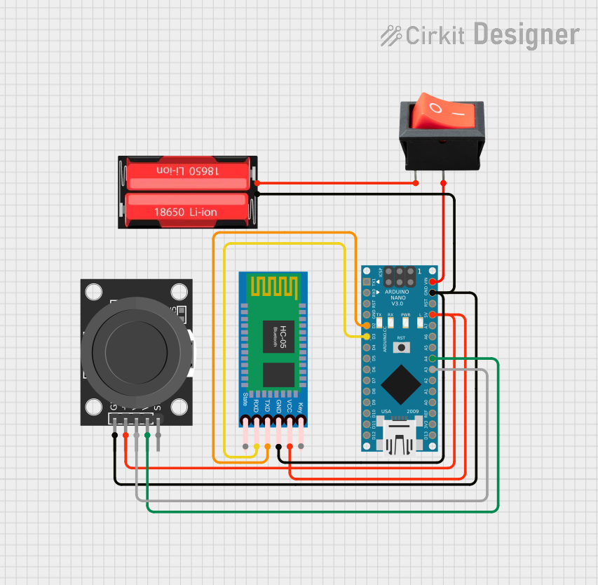
Arduino Nano Joystick-Controlled Bluetooth Module with Battery Power
Image of padelpro transmitter: A project utilizing KY-012 in a practical application
This circuit is a wireless joystick controller that uses an Arduino Nano to read analog signals from a KY-023 Dual Axis Joystick Module and transmits the data via an HC-05 Bluetooth Module. The system is powered by a 18650 Li-Ion battery with a rocker switch for power control.
Cirkit Designer LogoOpen Project in Cirkit Designer
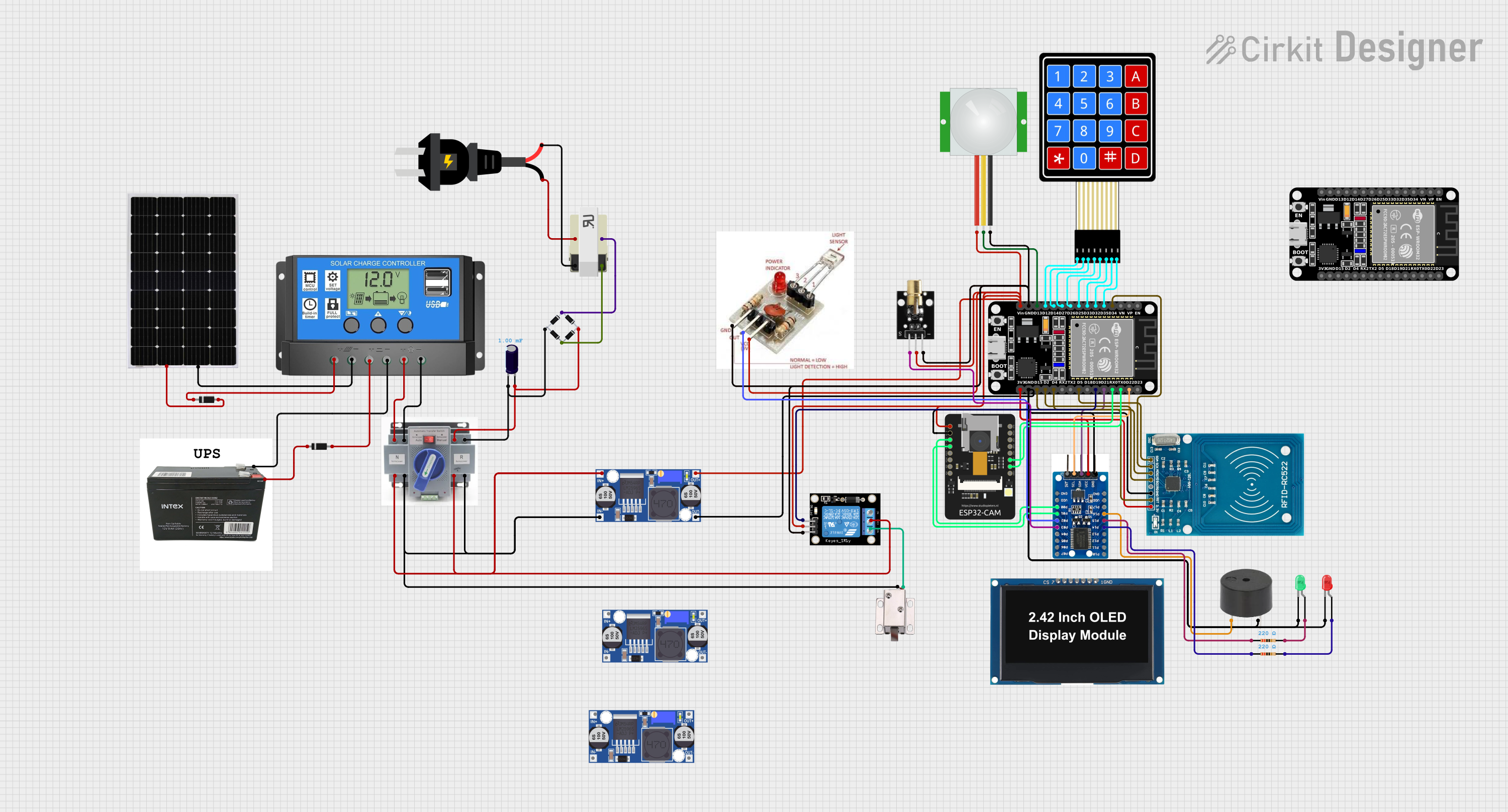
ESP32-Based Security System with RFID and Laser Tripwire
Image of CPE doorlock system: A project utilizing KY-012 in a practical application
This circuit is designed for a comprehensive security and access control system with motion detection, access via RFID, and a break-beam sensor. It includes a solenoid lock controlled by a relay, visual and audible alerts, and a robust power management system with solar and battery backup to ensure uninterrupted operation.
Cirkit Designer LogoOpen Project in Cirkit Designer
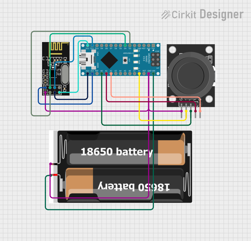
Wireless Joystick-Controlled Interface with Arduino Nano and NRF24L01
Image of Transmitter 11: A project utilizing KY-012 in a practical application
This circuit features an Arduino Nano interfaced with a KY-023 Dual Axis Joystick Module for analog input, and an NRF24L01 module for wireless communication. The joystick provides x and y-axis control signals to the Arduino's analog inputs and a switch signal to a digital input, while the NRF24L01 enables the Arduino to communicate with other devices wirelessly. The 2x 18650 batteries supply power to the Arduino, which in turn powers the joystick and the NRF24L01 module.
Cirkit Designer LogoOpen Project in Cirkit Designer
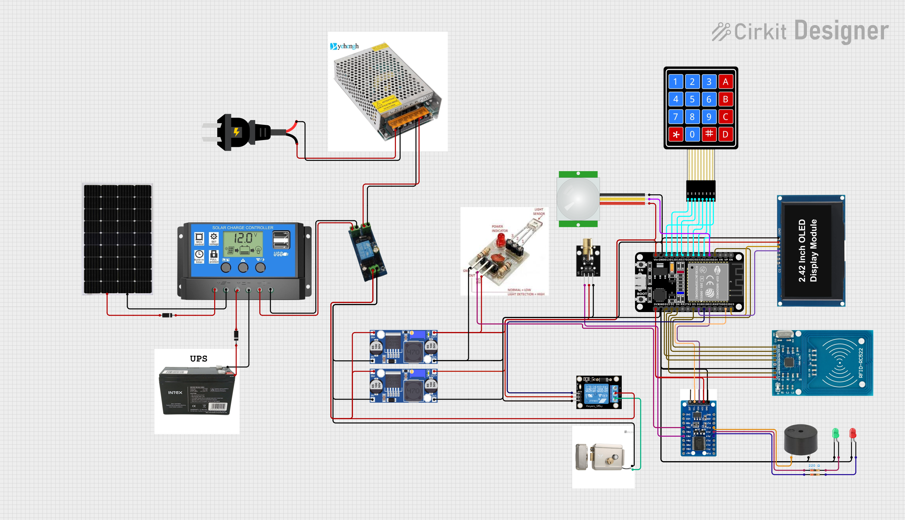
ESP32-Based Security System with RFID and Laser Intrusion Detection
Image of CPE doorlock system upgrade: A project utilizing KY-012 in a practical application
This circuit is a security and access control system featuring motion detection, laser beam-break sensing, and RFID scanning, interfaced with a keypad and visual/audible indicators, powered by a solar-charged battery, and capable of controlling an electric lock via a relay.
Cirkit Designer LogoOpen Project in Cirkit Designer

Explore Projects Built with KY-012

Use Cirkit Designer to design, explore, and prototype these projects online. Some projects support real-time simulation. Click "Open Project" to start designing instantly!
Image of padelpro transmitter: A project utilizing KY-012 in a practical application
Arduino Nano Joystick-Controlled Bluetooth Module with Battery Power
This circuit is a wireless joystick controller that uses an Arduino Nano to read analog signals from a KY-023 Dual Axis Joystick Module and transmits the data via an HC-05 Bluetooth Module. The system is powered by a 18650 Li-Ion battery with a rocker switch for power control.
Cirkit Designer LogoOpen Project in Cirkit Designer
Image of CPE doorlock system: A project utilizing KY-012 in a practical application
ESP32-Based Security System with RFID and Laser Tripwire
This circuit is designed for a comprehensive security and access control system with motion detection, access via RFID, and a break-beam sensor. It includes a solenoid lock controlled by a relay, visual and audible alerts, and a robust power management system with solar and battery backup to ensure uninterrupted operation.
Cirkit Designer LogoOpen Project in Cirkit Designer
Image of Transmitter 11: A project utilizing KY-012 in a practical application
Wireless Joystick-Controlled Interface with Arduino Nano and NRF24L01
This circuit features an Arduino Nano interfaced with a KY-023 Dual Axis Joystick Module for analog input, and an NRF24L01 module for wireless communication. The joystick provides x and y-axis control signals to the Arduino's analog inputs and a switch signal to a digital input, while the NRF24L01 enables the Arduino to communicate with other devices wirelessly. The 2x 18650 batteries supply power to the Arduino, which in turn powers the joystick and the NRF24L01 module.
Cirkit Designer LogoOpen Project in Cirkit Designer
Image of CPE doorlock system upgrade: A project utilizing KY-012 in a practical application
ESP32-Based Security System with RFID and Laser Intrusion Detection
This circuit is a security and access control system featuring motion detection, laser beam-break sensing, and RFID scanning, interfaced with a keypad and visual/audible indicators, powered by a solar-charged battery, and capable of controlling an electric lock via a relay.
Cirkit Designer LogoOpen Project in Cirkit Designer

Common Applications and Use Cases

  • Alarm Systems: Used to alert users of security breaches or other emergencies.
  • Timers: Provides audible alerts for countdowns or elapsed time.
  • User Interfaces: Offers feedback in electronic devices, such as button presses.
  • Educational Projects: Ideal for learning about sound generation and signal processing.

Technical Specifications

Key Technical Details

Parameter Value
Operating Voltage 3.3V - 5V
Current Consumption < 30mA
Sound Output 85dB at 10cm
Frequency Range 1.5kHz - 2.5kHz
Dimensions 18.5mm x 15mm x 11.5mm

Pin Configuration and Descriptions

Pin Number Pin Name Description
1 VCC Power supply (3.3V - 5V)
2 GND Ground
3 I/O Signal input (PWM or square wave)

Usage Instructions

How to Use the Component in a Circuit

  1. Power Connection: Connect the VCC pin to a 3.3V or 5V power supply.
  2. Ground Connection: Connect the GND pin to the ground of the power supply.
  3. Signal Input: Connect the I/O pin to a PWM-capable pin on a microcontroller (e.g., Arduino UNO).

Example Circuit Diagram

Arduino UNO          KY-012
-----------          ------
  5V  --------------> VCC
 GND --------------> GND
 Pin 9  ------------> I/O

Important Considerations and Best Practices

  • Signal Type: Ensure the signal input is a PWM or square wave to produce sound.
  • Voltage Levels: Do not exceed the operating voltage range (3.3V - 5V) to avoid damaging the module.
  • Frequency Range: Experiment with different frequencies within the 1.5kHz - 2.5kHz range to achieve the desired sound.

Sample Arduino Code

/*
 * KY-012 Passive Buzzer Example
 * This code generates a tone on the KY-012 buzzer using PWM on pin 9.
 */

const int buzzerPin = 9; // Pin connected to the I/O pin of KY-012

void setup() {
  pinMode(buzzerPin, OUTPUT); // Set the buzzer pin as an output
}

void loop() {
  tone(buzzerPin, 2000); // Generate a 2kHz tone
  delay(1000);           // Wait for 1 second
  noTone(buzzerPin);     // Stop the tone
  delay(1000);           // Wait for 1 second
}

Troubleshooting and FAQs

Common Issues Users Might Face

  1. No Sound Output:

    • Solution: Ensure the signal input is a PWM or square wave. Check the connections and verify the power supply voltage.
  2. Low Sound Volume:

    • Solution: Verify the operating voltage is within the specified range (3.3V - 5V). Experiment with different frequencies to achieve optimal sound output.
  3. Intermittent Sound:

    • Solution: Check for loose connections. Ensure the signal input is stable and continuous.

FAQs

Q1: Can I use the KY-012 with a 3.3V microcontroller?

  • A1: Yes, the KY-012 can operate within a voltage range of 3.3V to 5V.

Q2: What type of signal does the KY-012 require?

  • A2: The KY-012 requires a PWM or square wave signal to produce sound.

Q3: How can I change the tone of the buzzer?

  • A3: You can change the tone by varying the frequency of the PWM signal applied to the I/O pin.

Q4: Is the KY-012 suitable for continuous operation?

  • A4: Yes, but ensure the module does not overheat and is operated within the specified voltage range.

By following this documentation, users can effectively integrate the KY-012 passive piezoelectric buzzer module into their projects, ensuring reliable and optimal performance.