How to Use USB Plug: Examples, Pinouts, and Specs
Introduction
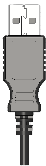
A USB plug is a standardized connector used to connect devices to a power source or to transfer data between devices. It is widely used in consumer electronics, computers, and mobile devices. USB plugs come in various types, including USB-A, USB-B, and USB-C, each designed for specific applications and compatibility. The USB standard ensures reliable power delivery and data transfer, making it a cornerstone of modern connectivity.
Explore Projects Built with USB Plug

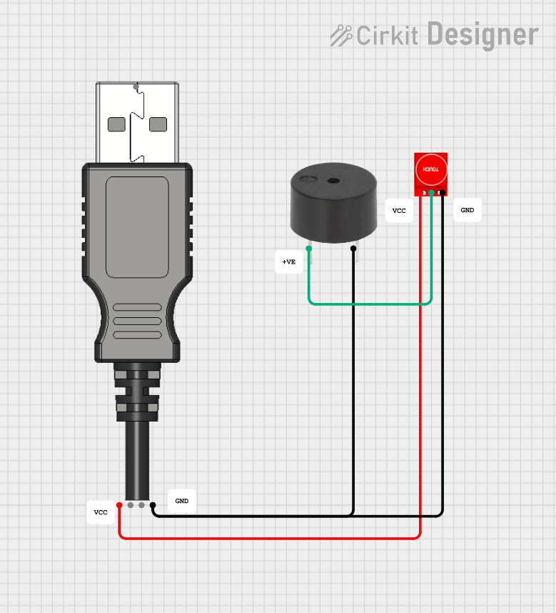


Explore Projects Built with USB Plug
Common Applications and Use Cases
- Charging mobile devices, tablets, and other electronics
- Data transfer between computers and peripherals (e.g., printers, external drives)
- Connecting input devices like keyboards and mice
- Powering small electronic projects and development boards (e.g., Arduino)
- Audio and video transmission in some USB-C implementations
Technical Specifications
General Specifications
| Parameter | Value/Description |
|---|---|
| Voltage (V) | 5V (standard), up to 20V for USB Power Delivery |
| Current (A) | 0.5A (USB 2.0), 0.9A (USB 3.0), up to 5A (USB-C) |
| Data Transfer Rate | Up to 480 Mbps (USB 2.0), 5 Gbps (USB 3.0), 10+ Gbps (USB-C) |
| Connector Types | USB-A, USB-B, USB-C, Micro-USB, Mini-USB |
| Durability | 1,500 to 10,000 insertion/removal cycles |
Pin Configuration and Descriptions
USB-A Plug
| Pin Number | Name | Description |
|---|---|---|
| 1 | VBUS | +5V power supply |
| 2 | D- | Data transfer (negative) |
| 3 | D+ | Data transfer (positive) |
| 4 | GND | Ground |
USB-C Plug
| Pin Number | Name | Description |
|---|---|---|
| A1, B1 | GND | Ground |
| A4, B4 | VBUS | +5V to +20V power supply |
| A6, B6 | D+ | Data transfer (positive) |
| A7, B7 | D- | Data transfer (negative) |
| A5, B5 | CC | Configuration channel for power and data roles |
| A8, B8 | SBU1, SBU2 | Sideband use (e.g., audio, alternate modes) |
Usage Instructions
How to Use the USB Plug in a Circuit
- Identify the USB Type: Determine the type of USB plug (e.g., USB-A, USB-C) required for your application.
- Connect Power and Ground: Use the VBUS and GND pins to supply power to your circuit. Ensure the voltage and current ratings match your device's requirements.
- Data Connections: For data transfer, connect the D+ and D- pins to the corresponding pins on the device or microcontroller.
- USB-C Specifics: If using USB-C, ensure proper configuration of the CC pins to negotiate power delivery and data roles.
Important Considerations and Best Practices
- Voltage and Current Ratings: Always verify the voltage and current requirements of your device to avoid damage.
- Cable Quality: Use high-quality USB cables to ensure reliable power delivery and data transfer.
- USB-C Power Delivery: For USB-C, use a compatible power delivery controller to negotiate higher voltages (up to 20V) if needed.
- Avoid Overloading: Do not exceed the current rating of the USB plug to prevent overheating or failure.
Example: Connecting a USB Plug to an Arduino UNO
The Arduino UNO can be powered via a USB-A plug. Below is an example of how to use a USB plug for power and data transfer.
// Example: Reading data from a USB-connected device on Arduino UNO
// Ensure the USB plug is connected to the Arduino's USB port for power and data.

void setup() {
  Serial.begin(9600); // Initialize serial communication at 9600 baud
  Serial.println("USB Plug Connected. Ready to receive data.");
}

void loop() {
  if (Serial.available() > 0) {
    // Read incoming data from the USB connection
    char receivedData = Serial.read();
    Serial.print("Received: ");
    Serial.println(receivedData);
  }
}
Troubleshooting and FAQs
Common Issues and Solutions
No Power Delivery
- Cause: Incorrect wiring or damaged cable.
- Solution: Verify the VBUS and GND connections. Test with a different cable.
Data Transfer Fails
- Cause: Misaligned D+ and D- connections or incompatible devices.
- Solution: Check the pin connections and ensure both devices support the same USB standard.
Overheating
- Cause: Excessive current draw or poor-quality cable.
- Solution: Use a cable rated for the required current. Reduce the load on the USB plug.
USB-C Device Not Recognized
- Cause: Missing or incorrect CC pin configuration.
- Solution: Use a USB-C controller IC to handle power and data role negotiation.
FAQs
Q: Can I use a USB plug to power a 12V device?
A: Standard USB plugs provide 5V. Use USB-C with Power Delivery for higher voltages, up to 20V.Q: How do I identify the type of USB plug I need?
A: Check the device's specifications or port shape. USB-A is rectangular, USB-C is oval, and USB-B is square.Q: Can I use a USB plug for both power and data simultaneously?
A: Yes, USB plugs are designed to handle both power delivery and data transfer concurrently.Q: What is the maximum current a USB plug can handle?
A: USB-C can handle up to 5A with Power Delivery, while USB-A typically supports up to 0.9A (USB 3.0).