How to Use PWR Meter 3 Click - 90A : Examples, Pinouts, and Specs
Introduction
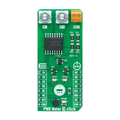
The PWR Meter 3 Click - 90A by Mikroe is a compact and efficient power measurement module designed for monitoring current up to 90A. It features an I2C interface, making it easy to integrate into microcontroller-based projects. This module is ideal for applications requiring precise power monitoring, such as energy management systems, industrial automation, and IoT devices.
Explore Projects Built with PWR Meter 3 Click - 90A


Explore Projects Built with PWR Meter 3 Click - 90A
Common Applications
- Energy consumption monitoring in smart homes and buildings
- Industrial equipment power usage tracking
- Battery management systems
- IoT devices requiring real-time power data
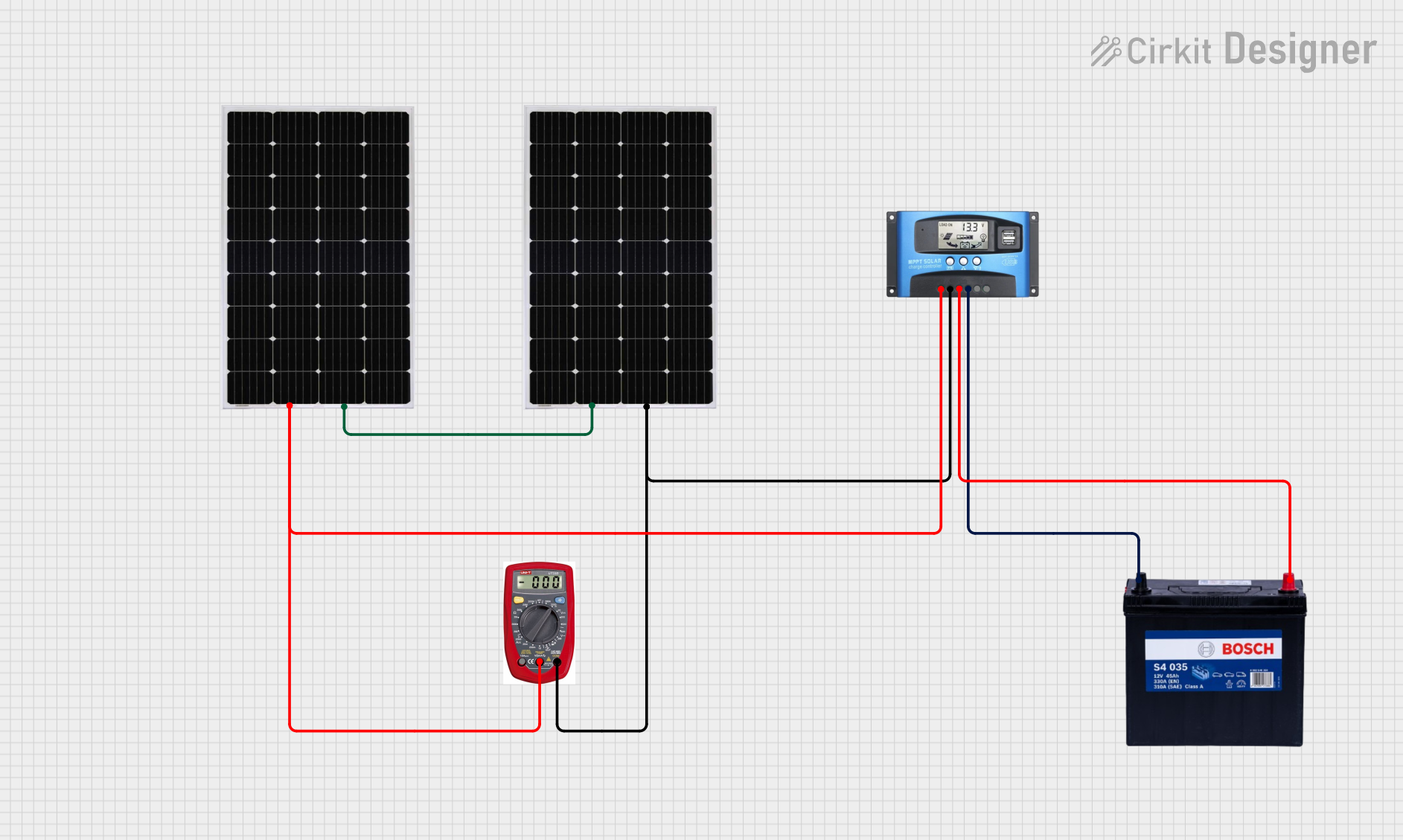
- Renewable energy systems (e.g., solar or wind power monitoring)
Technical Specifications
Key Technical Details
| Parameter | Value |
|---|---|
| Operating Voltage | 3.3V or 5V |
| Current Measurement Range | Up to ±90A |
| Communication Interface | I2C |
| Resolution | 16-bit |
| Accuracy | ±1% |
| Operating Temperature | -40°C to +85°C |
| Dimensions | 25.4mm x 25.4mm (1" x 1") |
Pin Configuration and Descriptions
The PWR Meter 3 Click module uses a standard 8-pin mikroBUS™ socket. Below is the pinout:
| Pin No. | Pin Name | Description |
|---|---|---|
| 1 | AN | Analog pin (not used in this module) |
| 2 | RST | Reset pin |
| 3 | CS | Chip Select (not used in this module) |
| 4 | SCK | Clock pin (not used in this module) |
| 5 | MISO | Master In Slave Out (not used) |
| 6 | MOSI | Master Out Slave In (not used) |
| 7 | 3.3V | Power supply (3.3V) |
| 8 | GND | Ground |
| 9 | SDA | I2C Data Line |
| 10 | SCL | I2C Clock Line |
| 11 | PWM | Pulse Width Modulation (not used) |
| 12 | INT | Interrupt pin (optional use) |
Usage Instructions
How to Use the Component in a Circuit
- Power Supply: Connect the module to a 3.3V or 5V power source via the mikroBUS™ socket.
- I2C Communication: Connect the SDA and SCL pins to the corresponding I2C pins on your microcontroller.
- Current Measurement: Pass the current-carrying wire through the onboard current sensor. Ensure the wire is properly aligned with the sensor for accurate readings.
- Microcontroller Integration: Use the I2C interface to read current, voltage, and power data from the module.
Important Considerations and Best Practices
- Current Range: Ensure the current being measured does not exceed the ±90A limit to avoid damage to the module.
- I2C Address: The default I2C address of the module is configurable. Refer to the datasheet for address selection details.
- Noise Reduction: For high-current applications, use proper shielding and grounding to minimize noise interference.
- Temperature: Operate the module within the specified temperature range (-40°C to +85°C) to maintain accuracy.
Example Code for Arduino UNO
Below is an example of how to interface the PWR Meter 3 Click with an Arduino UNO using the I2C interface:
#include <Wire.h>

// Define the I2C address of the PWR Meter 3 Click
#define PWR_METER_I2C_ADDRESS 0x40

void setup() {
  Wire.begin(); // Initialize I2C communication
  Serial.begin(9600); // Initialize serial communication for debugging

  // Print a message to indicate setup is complete
  Serial.println("PWR Meter 3 Click - Initialization Complete");
}

void loop() {
  Wire.beginTransmission(PWR_METER_I2C_ADDRESS); // Start communication
  Wire.write(0x00); // Request data from the power meter (register 0x00)
  Wire.endTransmission();

  Wire.requestFrom(PWR_METER_I2C_ADDRESS, 2); // Request 2 bytes of data
  if (Wire.available() == 2) {
    int rawData = Wire.read() << 8 | Wire.read(); // Combine two bytes
    float current = rawData * 0.01; // Convert raw data to current (example scaling)

    // Print the current reading to the serial monitor
    Serial.print("Current: ");
    Serial.print(current);
    Serial.println(" A");
  }

  delay(1000); // Wait 1 second before the next reading
}
Note: The scaling factor (0.01) in the code is an example. Refer to the module's datasheet for the correct conversion formula.
Troubleshooting and FAQs
Common Issues and Solutions
No Data on I2C Bus:
- Ensure the SDA and SCL lines are properly connected.
- Verify the I2C address matches the module's configuration.
- Check for loose connections or damaged wires.
Inaccurate Readings:
- Ensure the current-carrying wire is properly aligned with the sensor.
- Verify the module is operating within the specified temperature range.
- Minimize electrical noise by using proper shielding and grounding.
Module Not Powering On:
- Confirm the power supply voltage is within the 3.3V to 5V range.
- Check the mikroBUS™ socket connections for proper alignment.
FAQs
Q1: Can the module measure both AC and DC currents?
A1: Yes, the PWR Meter 3 Click can measure both AC and DC currents within the ±90A range.
Q2: What is the resolution of the current measurement?
A2: The module provides a 16-bit resolution for precise current measurements.
Q3: Can I use this module with a 5V microcontroller?
A3: Yes, the module supports both 3.3V and 5V logic levels, making it compatible with most microcontrollers.
Q4: How do I change the I2C address?
A4: Refer to the module's datasheet for instructions on configuring the I2C address using onboard jumpers or software commands.
Q5: Is the module suitable for high-frequency current measurements?
A5: The module is designed for general-purpose power monitoring. For high-frequency applications, additional filtering may be required.