How to Use mega motor drive: Examples, Pinouts, and Specs
Introduction
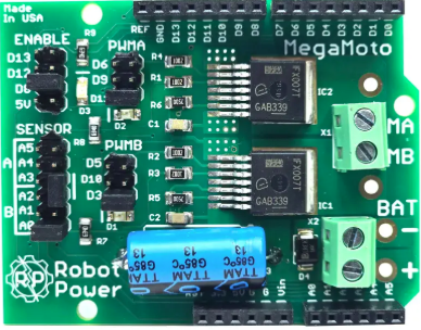
The Mega Motor Drive is a high-performance motor controller designed to drive large motors with precision and efficiency. It is widely used in robotics, industrial automation, and other applications requiring precise motor control. This component supports high current and voltage ratings, making it suitable for driving powerful DC motors, stepper motors, and other electromechanical systems. Its robust design ensures reliable operation in demanding environments.
Explore Projects Built with mega motor drive

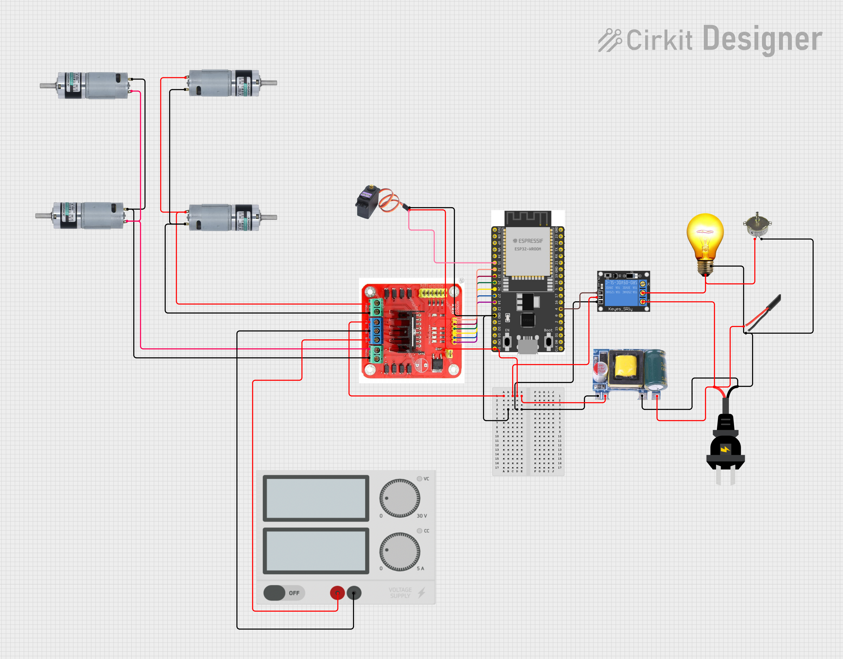


Explore Projects Built with mega motor drive
Common Applications
- Robotics (e.g., robotic arms, mobile robots)
- Industrial automation systems
- Conveyor belts and material handling
- Electric vehicles and carts
- CNC machines and 3D printers
Technical Specifications
The Mega Motor Drive is engineered to handle high-power motors with ease. Below are its key technical specifications:
| Parameter | Value |
|---|---|
| Operating Voltage Range | 12V to 48V |
| Maximum Continuous Current | 30A |
| Peak Current | 50A (for up to 10 seconds) |
| PWM Frequency | Up to 20 kHz |
| Control Interface | PWM, Direction, and Enable pins |
| Protection Features | Overcurrent, Overtemperature, and Undervoltage |
| Dimensions | 100mm x 60mm x 25mm |
| Weight | 150g |
Pin Configuration
The Mega Motor Drive has a straightforward pin layout for easy integration into your circuits. Below is the pin configuration:
| Pin Name | Description |
|---|---|
| VIN+ | Positive power supply input (12V to 48V) |
| VIN- | Negative power supply input (GND) |
| MOTOR+ | Positive terminal for the motor connection |
| MOTOR- | Negative terminal for the motor connection |
| PWM | Pulse Width Modulation input for speed control |
| DIR | Direction control input (High/Low) |
| EN | Enable input (High to enable, Low to disable) |
| GND | Ground reference for control signals |
Usage Instructions
How to Use the Mega Motor Drive in a Circuit
- Power Supply: Connect a suitable DC power supply to the
VIN+andVIN-pins. Ensure the voltage is within the 12V to 48V range. - Motor Connection: Connect the motor terminals to the
MOTOR+andMOTOR-pins. - Control Signals:
- Use the
PWMpin to control the motor speed. A higher duty cycle corresponds to a higher speed. - Use the
DIRpin to set the motor's rotation direction (e.g., High for clockwise, Low for counterclockwise). - Use the
ENpin to enable or disable the motor drive.
- Use the
- Ground Reference: Connect the
GNDpin to the ground of your control circuit (e.g., microcontroller).
Important Considerations
- Heat Dissipation: The Mega Motor Drive can generate significant heat during operation. Use a heatsink or active cooling if operating near the maximum current rating.
- Current Limiting: Ensure the motor's current draw does not exceed the drive's maximum continuous current rating to avoid damage.
- Protection Features: The drive includes built-in protection for overcurrent, overtemperature, and undervoltage. However, always design your circuit with proper fuses and safety measures.
Example: Connecting to an Arduino UNO
Below is an example of how to control the Mega Motor Drive using an Arduino UNO:
Circuit Connections
- Connect the
PWMpin of the Mega Motor Drive to Arduino pin 9. - Connect the
DIRpin to Arduino pin 8. - Connect the
ENpin to Arduino pin 7. - Connect the
GNDpin of the Mega Motor Drive to the Arduino GND. - Connect a 24V power supply to the
VIN+andVIN-pins. - Connect the motor to the
MOTOR+andMOTOR-pins.
Arduino Code
// Define pin connections
const int pwmPin = 9;  // PWM signal for speed control
const int dirPin = 8;  // Direction control
const int enPin = 7;   // Enable pin

void setup() {
  // Set pin modes
  pinMode(pwmPin, OUTPUT);
  pinMode(dirPin, OUTPUT);
  pinMode(enPin, OUTPUT);

  // Enable the motor driver
  digitalWrite(enPin, HIGH);
}

void loop() {
  // Set motor direction to clockwise
  digitalWrite(dirPin, HIGH);

  // Gradually increase motor speed
  for (int speed = 0; speed <= 255; speed++) {
    analogWrite(pwmPin, speed);  // Set PWM duty cycle
    delay(20);                   // Wait for 20ms
  }

  // Hold at full speed for 2 seconds
  delay(2000);

  // Gradually decrease motor speed
  for (int speed = 255; speed >= 0; speed--) {
    analogWrite(pwmPin, speed);  // Set PWM duty cycle
    delay(20);                   // Wait for 20ms
  }

  // Hold at zero speed for 2 seconds
  delay(2000);
}
Troubleshooting and FAQs
Common Issues
Motor Not Spinning:
- Ensure the
ENpin is set to HIGH to enable the motor drive. - Verify the power supply voltage is within the specified range.
- Check the motor connections to
MOTOR+andMOTOR-.
- Ensure the
Overheating:
- Ensure proper heat dissipation using a heatsink or fan.
- Check if the motor's current exceeds the drive's maximum rating.
Erratic Motor Behavior:
- Verify the PWM signal is clean and within the supported frequency range.
- Check for loose or faulty connections in the circuit.
FAQs
Q: Can I use the Mega Motor Drive with a stepper motor?
A: Yes, but you will need to generate the appropriate step and direction signals using a microcontroller or stepper motor driver.
Q: What happens if the motor draws more than 30A continuously?
A: The drive's overcurrent protection will activate, shutting down the motor to prevent damage.
Q: Can I use a 5V logic level for the control pins?
A: Yes, the control pins are compatible with 5V logic levels, making it easy to interface with microcontrollers like Arduino.
Q: Is reverse polarity protection included?
A: No, the Mega Motor Drive does not include reverse polarity protection. Always double-check your power supply connections.