How to Use Buck converter: Examples, Pinouts, and Specs
Introduction
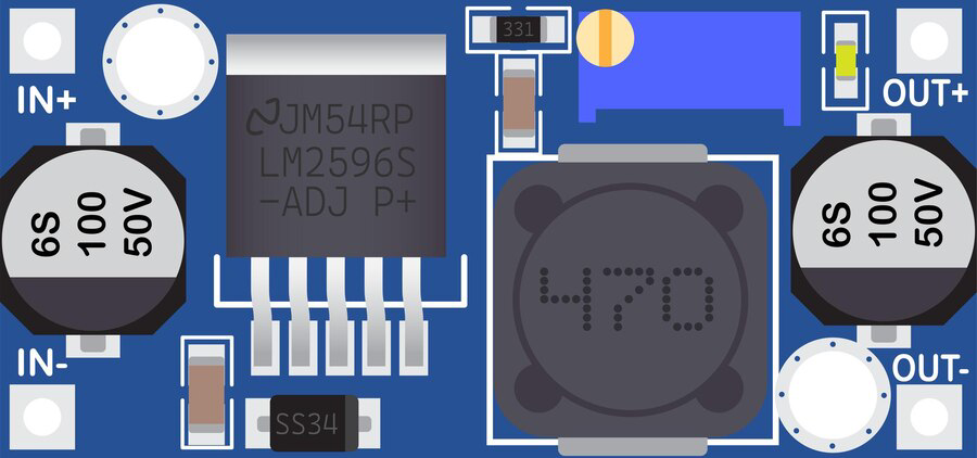
A buck converter, also known as a step-down converter, is an essential electronic component used to convert a higher direct current (DC) input voltage to a lower DC output voltage with high efficiency. This type of power converter is widely used in battery-operated devices, power supplies, and as voltage regulators in various electronic circuits. Its ability to provide a stable output voltage while conserving energy makes it a popular choice in portable electronics, automotive applications, and in systems that require extended battery life.
Explore Projects Built with Buck converter


Explore Projects Built with Buck converter
Technical Specifications
Key Technical Details
- Input Voltage Range: Typically ranges from a few volts above the desired output to several tens of volts.
- Output Voltage Range: Adjustable based on the design and external components used.
- Maximum Output Current: Depends on the specific model and cooling conditions.
- Efficiency: Generally between 80% to 95%, depending on load and input/output voltage difference.
- Switching Frequency: Can vary from tens of kHz to several MHz.
- Operating Temperature: Usually from -40°C to +85°C for industrial-grade components.
Pin Configuration and Descriptions
| Pin Number | Name | Description |
|---|---|---|
| 1 | VIN | Input voltage supply. Connect to the DC power source. |
| 2 | GND | Ground. Connect to the system ground. |
| 3 | VOUT | Output voltage. Connect to the load. |
| 4 | ENABLE | Enables or disables the converter. Typically pulled high to enable. |
| 5 | FEEDBACK (FB) | Feedback pin for output voltage regulation. Connected to a voltage divider. |
| 6 | SWITCH NODE (SW) | Switching node. Connects to the inductor. |
Usage Instructions
How to Use the Buck Converter in a Circuit
- Input Supply Connection: Connect the positive terminal of your DC power source to the VIN pin and the negative terminal to the GND pin.
- Output Load Connection: Connect your load to the VOUT pin and the other side of the load to GND.
- Feedback Network: Connect a voltage divider from VOUT to FB to GND to set the output voltage. The values of the resistors in the divider will determine the output voltage based on the converter's reference voltage.
- Enable Pin: If the buck converter has an ENABLE pin, connect it to a logic high level to turn on the converter. If you want to control the converter with a microcontroller like an Arduino, connect this pin to one of the digital I/O pins.
Important Considerations and Best Practices
- Heat Management: Ensure adequate cooling for the buck converter, as efficiency losses manifest as heat.
- Input Capacitor: Place a capacitor close to the VIN and GND pins to stabilize the input supply and reduce voltage spikes.
- Output Capacitor: Use an output capacitor to smooth out the voltage ripple and provide a stable output.
- Inductor Selection: Choose an inductor with an appropriate current rating and low series resistance for better efficiency.
- Switching Frequency: Higher frequencies allow for smaller inductors and capacitors but can increase losses and EMI.
Troubleshooting and FAQs
Common Issues
- Output Voltage Too Low or High: Check the feedback network and ensure the resistors are correctly sized and connected.
- Excessive Heat: Verify that the current draw is within the converter's limits and improve cooling if necessary.
- Voltage Ripple: Increase the size of the output capacitor or check for proper inductor selection.
Solutions and Tips
- Inadequate Output: If the output is not stable, ensure that the input voltage is sufficient and that all connections are secure.
- Noise Issues: If noise is a concern, add a ferrite bead on the input line and ensure proper layout practices to minimize EMI.
FAQs
Q: Can I use a buck converter to charge batteries? A: Yes, but ensure that the output voltage is appropriate for the battery and that you include proper charging circuitry.
Q: What happens if I reverse the input polarity? A: Reversing the input polarity can damage the buck converter. Always double-check connections before powering up.
Q: How do I choose the right inductor and capacitor values? A: Inductor and capacitor values depend on the desired output current, voltage, ripple, and switching frequency. Use the manufacturer's recommendations as a starting point.
Q: Can I adjust the output voltage? A: Yes, by changing the resistor values in the feedback network, you can adjust the output voltage.
Example Arduino Code
// Example code to control a buck converter's ENABLE pin using an Arduino UNO

const int enablePin = 7; // Connect the ENABLE pin of the buck converter to digital pin 7

void setup() {
  pinMode(enablePin, OUTPUT); // Set the enable pin as an output
}

void loop() {
  digitalWrite(enablePin, HIGH); // Enable the buck converter
  delay(5000); // Wait for 5 seconds
  digitalWrite(enablePin, LOW); // Disable the buck converter
  delay(5000); // Wait for 5 seconds
}
Note: This code is a simple example to turn the buck converter on and off. In a real-world application, you would use feedback from the output voltage to adjust the ENABLE pin dynamically or use a PWM signal to control the output voltage if the buck converter supports such a feature.