How to Use Rotary Encoder: Examples, Pinouts, and Specs
Introduction
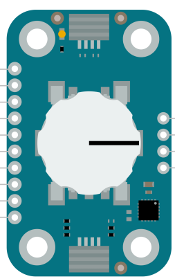
The Rotary Encoder (Arduino ABX00107) is an electromechanical device designed to convert the angular position or motion of a shaft into an analog or digital signal. This versatile component is widely used for position sensing, control systems, and user input in various applications. Unlike potentiometers, rotary encoders can rotate continuously without limits, making them ideal for applications requiring infinite rotation or precise incremental adjustments.
Explore Projects Built with Rotary Encoder
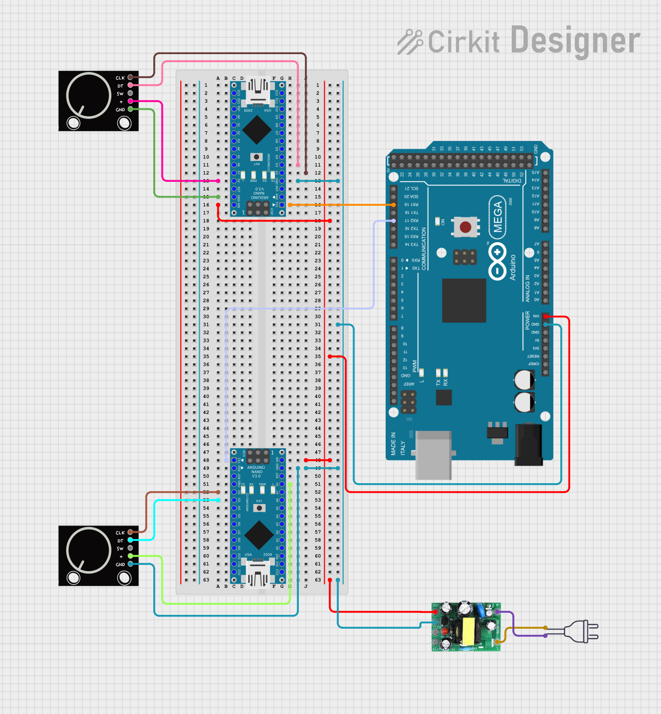
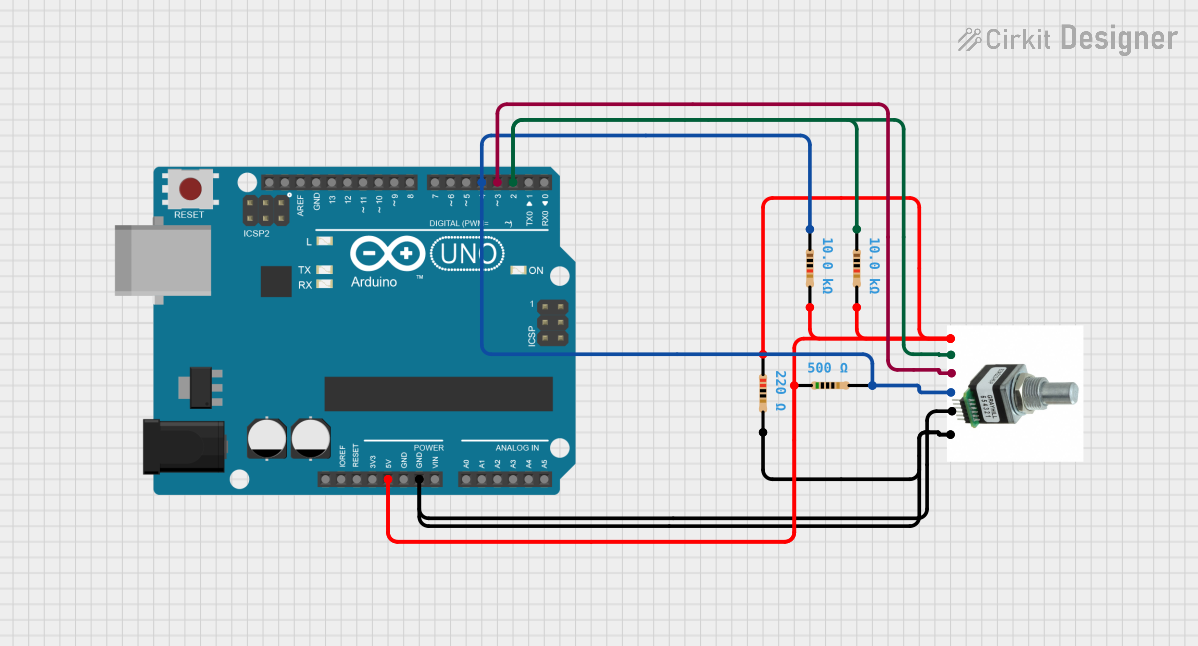
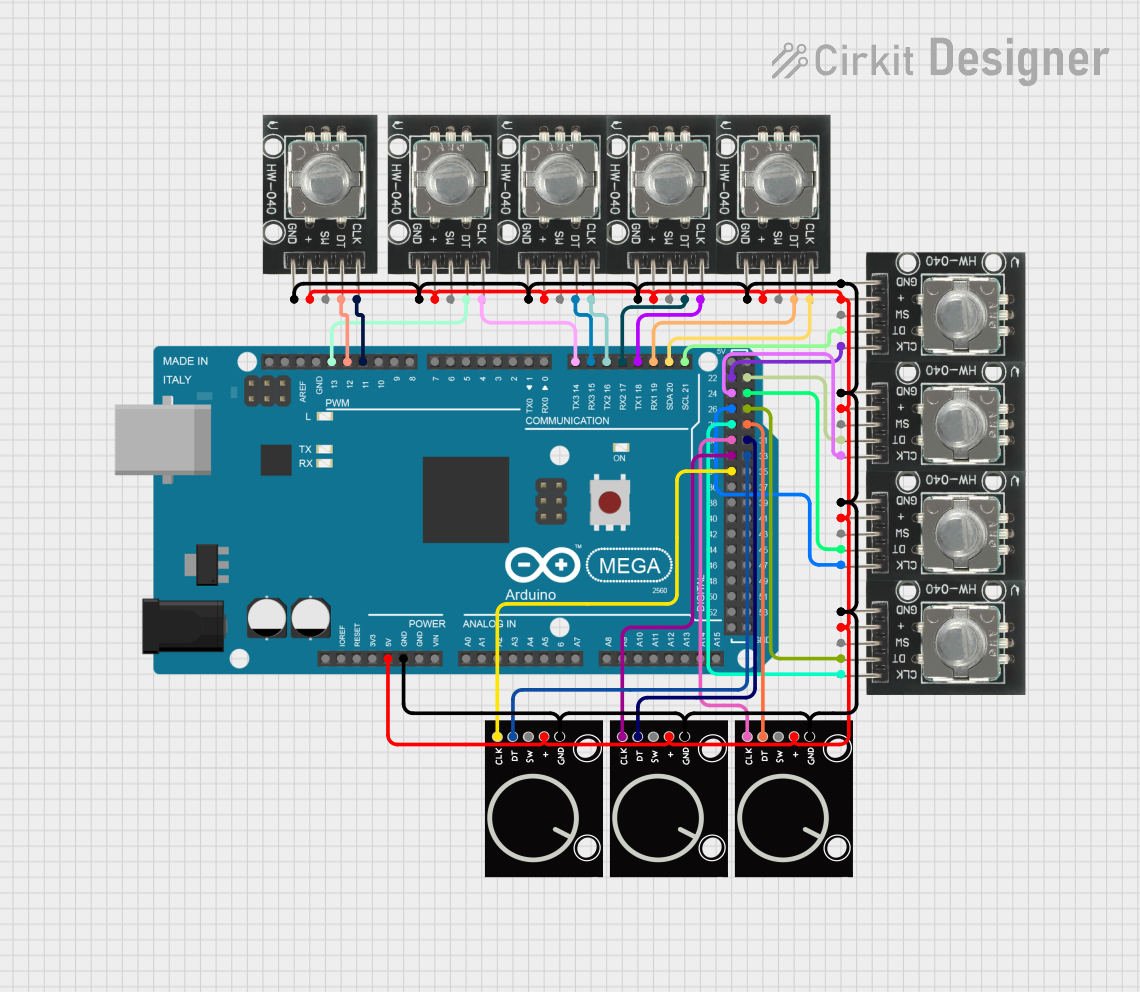
Explore Projects Built with Rotary Encoder
Common Applications
- Volume and menu control in audio and video equipment
- Robotics for position and motion sensing
- Industrial automation for motor control
- User input devices such as knobs and dials
- CNC machines and 3D printers for precise positioning
Technical Specifications
The following table outlines the key technical details of the Arduino ABX00107 Rotary Encoder:
| Parameter | Specification |
|---|---|
| Manufacturer | Arduino |
| Part ID | ABX00107 |
| Operating Voltage | 5V |
| Output Signal | Digital (Quadrature: A and B phases) |
| Maximum Rotational Speed | 100 RPM (recommended) |
| Shaft Type | Continuous rotation |
| Detents | 20 detents per revolution |
| Push Button | Integrated (momentary switch) |
| Operating Temperature | -20°C to 70°C |
| Dimensions | 11.5mm x 12.5mm x 15.5mm |
Pin Configuration and Descriptions
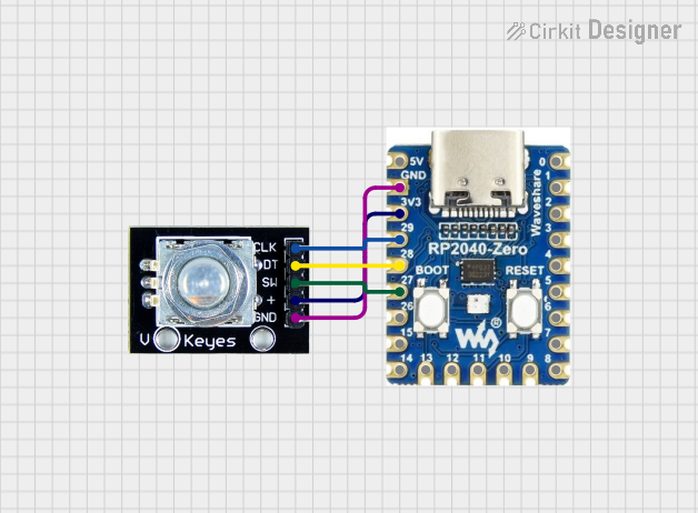
The rotary encoder has five pins, as described in the table below:
| Pin | Name | Description |
|---|---|---|
| 1 | GND | Ground connection |
| 2 | +5V | Power supply (5V) |
| 3 | SW | Push button output (active LOW) |
| 4 | DT | Data signal (B phase of quadrature output) |
| 5 | CLK | Clock signal (A phase of quadrature output) |
Usage Instructions
How to Use the Rotary Encoder in a Circuit
- Power Connections: Connect the
+5Vpin to the 5V output of your microcontroller and theGNDpin to ground. - Signal Connections:
- Connect the
CLKpin to a digital input pin on your microcontroller. - Connect the
DTpin to another digital input pin. - If using the push button, connect the
SWpin to a digital input pin with a pull-up resistor.
- Connect the
- Debouncing: Rotary encoders may produce noisy signals due to mechanical contacts. Use software debouncing or external capacitors to filter the signals.
Arduino UNO Example Code
Below is an example code snippet for interfacing the rotary encoder with an Arduino UNO:
// Rotary Encoder Example Code for Arduino UNO
// Manufacturer: Arduino
// Part ID: ABX00107

#define CLK 2  // Connect CLK pin to digital pin 2
#define DT 3   // Connect DT pin to digital pin 3
#define SW 4   // Connect SW pin to digital pin 4

int counter = 0;  // Variable to store the encoder position
int currentStateCLK;
int lastStateCLK;
bool buttonPressed = false;

void setup() {
  pinMode(CLK, INPUT);
  pinMode(DT, INPUT);
  pinMode(SW, INPUT_PULLUP);  // Use internal pull-up resistor for the button
  Serial.begin(9600);

  // Read the initial state of CLK
  lastStateCLK = digitalRead(CLK);
}

void loop() {
  // Read the current state of CLK
  currentStateCLK = digitalRead(CLK);

  // If the state of CLK has changed, a rotation has occurred
  if (currentStateCLK != lastStateCLK) {
    // Determine the direction of rotation
    if (digitalRead(DT) != currentStateCLK) {
      counter++;  // Clockwise rotation
    } else {
      counter--;  // Counterclockwise rotation
    }

    // Print the updated counter value
    Serial.print("Position: ");
    Serial.println(counter);
  }

  // Update the last state of CLK
  lastStateCLK = currentStateCLK;

  // Check if the button is pressed
  if (digitalRead(SW) == LOW) {
    if (!buttonPressed) {
      Serial.println("Button Pressed!");
      buttonPressed = true;
    }
  } else {
    buttonPressed = false;
  }
}
Important Considerations and Best Practices
- Pull-up Resistors: Ensure the
SWpin is connected to a pull-up resistor (internal or external) to avoid floating states. - Debouncing: Use software or hardware debouncing to ensure stable readings from the encoder.
- Signal Filtering: For high-speed applications, consider adding capacitors to the
CLKandDTlines to reduce noise. - Mechanical Wear: Avoid excessive force or speed to prevent mechanical wear and ensure long-term reliability.
Troubleshooting and FAQs
Common Issues
Unstable or Erratic Readings:
- Cause: Signal noise or lack of debouncing.
- Solution: Implement software debouncing or add capacitors to the signal lines.
No Response from the Encoder:
- Cause: Incorrect wiring or loose connections.
- Solution: Double-check all connections and ensure proper power supply.
Push Button Not Working:
- Cause: Missing pull-up resistor or incorrect pin configuration.
- Solution: Use an internal or external pull-up resistor and verify the pin setup in the code.
Incorrect Direction Detection:
- Cause: Swapped
CLKandDTconnections. - Solution: Reverse the connections of the
CLKandDTpins.
- Cause: Swapped
FAQs
Q1: Can the rotary encoder be used with 3.3V systems?
A1: The Arduino ABX00107 is designed for 5V operation. For 3.3V systems, use a level shifter or ensure compatibility with the microcontroller's input voltage range.
Q2: How many detents does the encoder have per revolution?
A2: The encoder has 20 detents per revolution, providing precise incremental control.
Q3: Can the encoder be used for high-speed applications?
A3: The recommended maximum rotational speed is 100 RPM. For higher speeds, ensure proper signal filtering and processing.
Q4: Is the push button momentary or latching?
A4: The push button is momentary, meaning it only remains active while pressed.
By following this documentation, users can effectively integrate the Arduino ABX00107 Rotary Encoder into their projects for reliable and precise control.