
How to Use Poe Switch 4 port: Examples, Pinouts, and Specs
 Design with Poe Switch 4 port in Cirkit Designer
Introduction
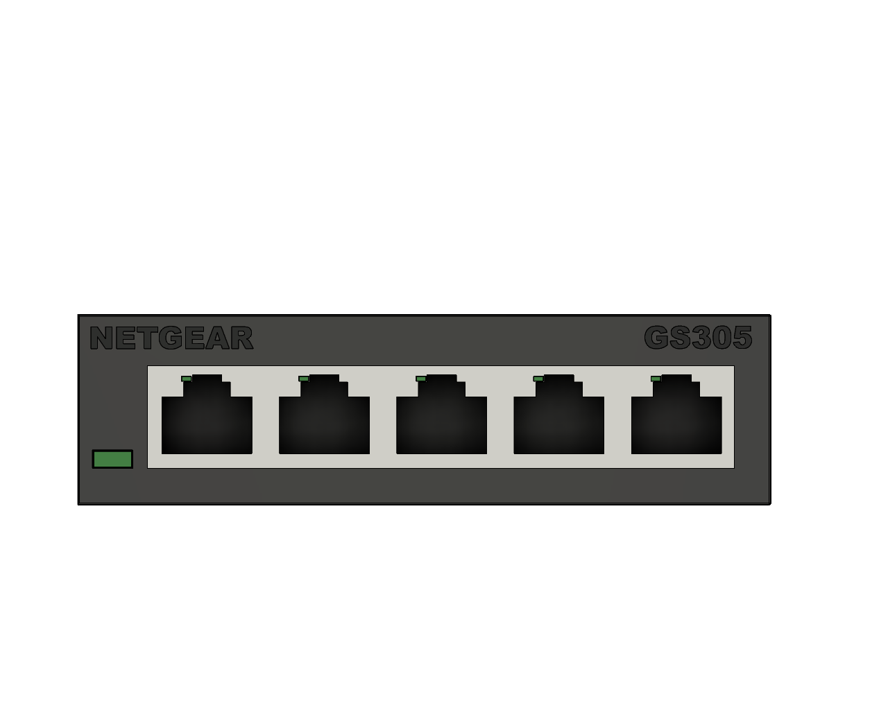
The Netgear GS305 is a 4-port Power over Ethernet (PoE) switch designed to simplify network setups by delivering both data and electrical power over a single Ethernet cable. This compact and reliable switch is ideal for powering devices such as IP cameras, wireless access points, VoIP phones, and other PoE-enabled devices, eliminating the need for separate power adapters.
Explore Projects Built with Poe Switch 4 port
 Open Project in Cirkit Designer
 Open Project in Cirkit Designer
 Open Project in Cirkit Designer
 Open Project in Cirkit Designer
Explore Projects Built with Poe Switch 4 port
Open Project in Cirkit DesignerOpen Project in Cirkit DesignerOpen Project in Cirkit DesignerOpen Project in Cirkit DesignerCommon Applications and Use Cases
- IP Surveillance Systems: Powering and connecting IP cameras in security setups.
- Wireless Networks: Supplying power and data to wireless access points.
- VoIP Systems: Connecting and powering VoIP phones in office environments.
- IoT Deployments: Enabling smart devices in industrial or home automation systems.
- Small Office/Home Office (SOHO): Simplifying network setups with minimal cabling.
Technical Specifications
Key Technical Details
| Specification | Details |
|---|---|
| Manufacturer | Netgear |
| Model | GS305 |
| Number of Ports | 4 PoE ports + 1 uplink port |
| PoE Standard | IEEE 802.3af (PoE) and IEEE 802.3at (PoE+) |
| PoE Budget | 63W total power budget |
| Data Transfer Rate | 10/100/1000 Mbps (Gigabit Ethernet) |
| Power Input | External power adapter (included) |
| Switching Capacity | 10 Gbps |
| Operating Temperature | 0°C to 40°C (32°F to 104°F) |
| Dimensions | 158 x 101 x 29 mm (6.2 x 4.0 x 1.1 inches) |
| Weight | 0.26 kg (0.57 lbs) |
| Certifications | CE, FCC, RoHS |
Port Configuration and Descriptions
| Port Number | Type | Description |
|---|---|---|
| 1-4 | PoE Gigabit Port | Provides both power and data to connected PoE-enabled devices. |
| 5 | Uplink Port | Non-PoE Gigabit Ethernet port for connecting to a router or another switch. |
| Power Input | DC Jack | Connects to the external power adapter to supply power to the switch. |
Usage Instructions
How to Use the Component in a Network
Setup and Placement:
- Place the GS305 switch on a flat, stable surface or mount it on a wall using the provided mounting holes.
- Ensure proper ventilation around the switch to prevent overheating.
Connecting Devices:
- Use Ethernet cables to connect PoE-enabled devices (e.g., IP cameras, access points) to ports 1-4.
- Connect the uplink port (port 5) to your router or another switch for network connectivity.
Powering the Switch:
- Plug the included power adapter into the DC input jack on the switch.
- Connect the adapter to a power outlet. The switch will power on automatically.
Verifying Connections:
- Check the LED indicators on the switch:
- Power LED: Indicates the switch is powered on.
- PoE LEDs: Lit when a device is successfully powered via PoE.
- Link/Activity LEDs: Indicate active data transmission on each port.
- Check the LED indicators on the switch:
Important Considerations and Best Practices
- Cable Requirements: Use Cat5e or higher Ethernet cables for optimal performance and PoE delivery.
- PoE Budget: Ensure the total power consumption of connected devices does not exceed the 63W PoE budget.
- Device Compatibility: Verify that connected devices support IEEE 802.3af or 802.3at standards.
- Surge Protection: Use a surge protector to safeguard the switch and connected devices from power surges.
Example: Connecting to an Arduino UNO with Ethernet Shield
While the GS305 does not directly interface with microcontrollers like the Arduino UNO, it can be used to provide network connectivity to an Arduino UNO equipped with an Ethernet shield. Below is an example of Arduino code to send data over the network:
#include <SPI.h>
#include <Ethernet.h>

// MAC address and IP address for the Ethernet shield
byte mac[] = { 0xDE, 0xAD, 0xBE, 0xEF, 0xFE, 0xED };
IPAddress ip(192, 168, 1, 177); // Replace with your desired IP address

// Initialize the Ethernet server on port 80
EthernetServer server(80);

void setup() {
  // Start the Ethernet connection
  Ethernet.begin(mac, ip);

  // Start the server
  server.begin();
  Serial.begin(9600);
  Serial.println("Server is ready at IP: ");
  Serial.println(Ethernet.localIP());
}

void loop() {
  // Listen for incoming clients
  EthernetClient client = server.available();
  if (client) {
    Serial.println("New client connected");
    while (client.connected()) {
      if (client.available()) {
        char c = client.read();
        Serial.write(c); // Echo received data to the Serial Monitor
        // Respond to the client
        client.println("Hello from Arduino!");
      }
    }
    client.stop();
    Serial.println("Client disconnected");
  }
}
Note: Connect the Ethernet shield to one of the GS305's PoE ports for data transmission. The Ethernet shield does not draw power via PoE, so it must be powered separately.
Troubleshooting and FAQs
Common Issues and Solutions
| Issue | Solution |
|---|---|
| No Power LED | Ensure the power adapter is securely connected to the switch and outlet. |
| No PoE Power to Devices | Verify that the connected device supports IEEE 802.3af/802.3at standards. |
| Intermittent Connectivity | Check Ethernet cables for damage and ensure they meet Cat5e or higher specs. |
| Overloaded PoE Budget | Disconnect devices to ensure the total power draw does not exceed 63W. |
| No Network Connectivity | Confirm the uplink port is connected to a router or another active switch. |
FAQs
Can I use non-PoE devices with the GS305?
- Yes, the GS305 supports both PoE and non-PoE devices. Non-PoE devices will only receive data.
What happens if I exceed the PoE budget?
- The switch will prioritize power delivery to connected devices based on port order (1-4). Devices exceeding the budget may not power on.
Is the GS305 managed or unmanaged?
- The GS305 is an unmanaged switch, meaning it does not support advanced configuration or management features.
Can I daisy-chain multiple GS305 switches?
- Yes, you can connect multiple switches using the uplink port, but ensure the network topology avoids loops.
By following this documentation, users can effectively set up and operate the Netgear GS305 PoE switch for various networking applications.