Cirkit Designer Logo
Cirkit Designer
Your all-in-one circuit design IDE
Home / 
Component Documentation

How to Use ms5611: Examples, Pinouts, and Specs

Image of ms5611
Cirkit Designer LogoDesign with ms5611 in Cirkit Designer

Introduction

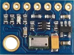
The MS5611 is a high-resolution barometric pressure sensor designed for precise altitude and pressure measurements. It features a digital output interface, making it easy to integrate into various systems. The sensor is widely used in applications such as weather stations, drones, altimeters, and other devices requiring accurate environmental data. Its compact size and low power consumption make it ideal for portable and embedded systems.

Explore Projects Built with ms5611

Use Cirkit Designer to design, explore, and prototype these projects online. Some projects support real-time simulation. Click "Open Project" to start designing instantly!
Arduino Mega 2560 Based Security System with Fingerprint Authentication and SMS Alerts
Image of Door security system: A project utilizing ms5611 in a practical application
This circuit features an Arduino Mega 2560 microcontroller interfaced with a SIM800L GSM module, two fingerprint scanners, an I2C LCD display, an IR sensor, and a piezo buzzer. Power management is handled by a PowerBoost 1000 Basic Pad USB, a TP4056 charging module, and a Li-ion 18650 battery, with an option to use a Mini AC-DC 110V-230V to 5V 700mA module for direct power supply. The primary functionality appears to be a security system with GSM communication capabilities, biometric access control, and visual/audible feedback.
Cirkit Designer LogoOpen Project in Cirkit Designer
Battery-Powered Emergency Alert System with NUCLEO-F072RB, SIM800L, and GPS NEO 6M
Image of women safety: A project utilizing ms5611 in a practical application
This circuit is an emergency alert system that uses a NUCLEO-F072RB microcontroller to send SMS alerts and make calls via a SIM800L GSM module, while obtaining location data from a GPS NEO 6M module. The system is powered by a Li-ion battery and includes a TP4056 module for battery charging and protection, with a rocker switch to control power to the microcontroller.
Cirkit Designer LogoOpen Project in Cirkit Designer
ESP8266 and SIM800L Based GPS Tracker with I2C LCD Display and Battery Power
Image of Little Innovator Competition: A project utilizing ms5611 in a practical application
This circuit integrates an ESP8266 NodeMCU microcontroller with a SIM800L GSM module, a GPS NEO 6M module, and a 16x2 I2C LCD display for communication and location tracking. It also includes a pushbutton for user input, a piezo buzzer for audio alerts, and is powered by a 2x 18650 battery pack through an LM2596 step-down module.
Cirkit Designer LogoOpen Project in Cirkit Designer
Solar-Powered GSM/GPRS+GPS Tracker with Seeeduino XIAO
Image of SOS System : A project utilizing ms5611 in a practical application
This circuit features an Ai Thinker A9G development board for GSM/GPRS and GPS/BDS connectivity, interfaced with a Seeeduino XIAO microcontroller for control and data processing. A solar cell, coupled with a TP4056 charging module, charges a 3.3V battery, which powers the system through a 3.3V regulator ensuring stable operation. The circuit likely serves for remote data communication and location tracking, with the capability to be powered by renewable energy and interfaced with additional sensors or input devices via the Seeeduino XIAO.
Cirkit Designer LogoOpen Project in Cirkit Designer

Explore Projects Built with ms5611

Use Cirkit Designer to design, explore, and prototype these projects online. Some projects support real-time simulation. Click "Open Project" to start designing instantly!
Image of Door security system: A project utilizing ms5611 in a practical application
Arduino Mega 2560 Based Security System with Fingerprint Authentication and SMS Alerts
This circuit features an Arduino Mega 2560 microcontroller interfaced with a SIM800L GSM module, two fingerprint scanners, an I2C LCD display, an IR sensor, and a piezo buzzer. Power management is handled by a PowerBoost 1000 Basic Pad USB, a TP4056 charging module, and a Li-ion 18650 battery, with an option to use a Mini AC-DC 110V-230V to 5V 700mA module for direct power supply. The primary functionality appears to be a security system with GSM communication capabilities, biometric access control, and visual/audible feedback.
Cirkit Designer LogoOpen Project in Cirkit Designer
Image of women safety: A project utilizing ms5611 in a practical application
Battery-Powered Emergency Alert System with NUCLEO-F072RB, SIM800L, and GPS NEO 6M
This circuit is an emergency alert system that uses a NUCLEO-F072RB microcontroller to send SMS alerts and make calls via a SIM800L GSM module, while obtaining location data from a GPS NEO 6M module. The system is powered by a Li-ion battery and includes a TP4056 module for battery charging and protection, with a rocker switch to control power to the microcontroller.
Cirkit Designer LogoOpen Project in Cirkit Designer
Image of Little Innovator Competition: A project utilizing ms5611 in a practical application
ESP8266 and SIM800L Based GPS Tracker with I2C LCD Display and Battery Power
This circuit integrates an ESP8266 NodeMCU microcontroller with a SIM800L GSM module, a GPS NEO 6M module, and a 16x2 I2C LCD display for communication and location tracking. It also includes a pushbutton for user input, a piezo buzzer for audio alerts, and is powered by a 2x 18650 battery pack through an LM2596 step-down module.
Cirkit Designer LogoOpen Project in Cirkit Designer
Image of SOS System : A project utilizing ms5611 in a practical application
Solar-Powered GSM/GPRS+GPS Tracker with Seeeduino XIAO
This circuit features an Ai Thinker A9G development board for GSM/GPRS and GPS/BDS connectivity, interfaced with a Seeeduino XIAO microcontroller for control and data processing. A solar cell, coupled with a TP4056 charging module, charges a 3.3V battery, which powers the system through a 3.3V regulator ensuring stable operation. The circuit likely serves for remote data communication and location tracking, with the capability to be powered by renewable energy and interfaced with additional sensors or input devices via the Seeeduino XIAO.
Cirkit Designer LogoOpen Project in Cirkit Designer

Technical Specifications

The MS5611 offers exceptional performance with the following key specifications:

  • Pressure Range: 10 to 1200 mbar
  • Resolution: Up to 0.012 mbar
  • Operating Voltage: 1.8V to 3.6V
  • Current Consumption: 1.25 µA (standby), 1.4 mA (active during conversion)
  • Interface: I²C (up to 400 kHz) and SPI (up to 20 MHz)
  • Operating Temperature Range: -40°C to +85°C
  • Dimensions: 5.0 mm x 3.0 mm x 1.0 mm

Pin Configuration and Descriptions

The MS5611 has 6 pins, as described in the table below:

Pin Name Description
1 VDD Power supply input (1.8V to 3.6V)
2 GND Ground connection
3 SCL/SPC Serial clock line for I²C or SPI clock input
4 SDA/SDI/SDO Data line for I²C or SPI data input/output
5 CSB Chip select for SPI (active low); connect to VDD for I²C mode
6 PS Protocol select: Connect to GND for SPI mode or VDD for I²C mode

Usage Instructions

How to Use the MS5611 in a Circuit

  1. Power Supply: Connect the VDD pin to a 3.3V power source and the GND pin to ground.
  2. Protocol Selection:
    • For I²C mode, connect the PS pin to VDD and the CSB pin to VDD.
    • For SPI mode, connect the PS pin to GND and use the CSB pin as the chip select.
  3. Communication Interface:
    • For I²C, connect the SCL and SDA pins to the corresponding I²C lines on your microcontroller.
    • For SPI, connect the SPC (clock), SDI/SDO (data), and CSB (chip select) pins to the SPI lines on your microcontroller.
  4. Pull-Up Resistors: If using I²C, ensure pull-up resistors (typically 4.7 kΩ) are connected to the SCL and SDA lines.
  5. Bypass Capacitor: Place a 0.1 µF capacitor close to the VDD pin for noise filtering.

Important Considerations and Best Practices

  • Ensure the operating voltage does not exceed 3.6V to avoid damaging the sensor.
  • Use proper decoupling capacitors to minimize noise and improve stability.
  • Avoid exposing the sensor to extreme environmental conditions beyond its specified range.
  • Calibrate the sensor in your application for the most accurate results.

Example Code for Arduino UNO

Below is an example of how to interface the MS5611 with an Arduino UNO using the I²C protocol:

#include <Wire.h>

// MS5611 I2C address
#define MS5611_ADDRESS 0x77

// Function to read 16-bit data from the sensor
uint16_t read16(uint8_t reg) {
  Wire.beginTransmission(MS5611_ADDRESS);
  Wire.write(reg); // Send register address
  Wire.endTransmission();
  delay(10); // Wait for the sensor to process the request

  Wire.requestFrom(MS5611_ADDRESS, 2); // Request 2 bytes of data
  uint16_t value = (Wire.read() << 8) | Wire.read(); // Combine MSB and LSB
  return value;
}

void setup() {
  Wire.begin(); // Initialize I2C communication
  Serial.begin(9600); // Start serial communication for debugging

  Serial.println("MS5611 Sensor Initialization");
}

void loop() {
  uint16_t pressure = read16(0x48); // Example register for pressure data
  Serial.print("Pressure: ");
  Serial.print(pressure);
  Serial.println(" mbar");

  delay(1000); // Wait 1 second before the next reading
}

Note: Replace 0x48 with the actual register address for pressure data as per the MS5611 datasheet.

Troubleshooting and FAQs

Common Issues and Solutions

  1. No Data from the Sensor:

    • Ensure the correct I²C or SPI address is used.
    • Verify the wiring and connections, especially the pull-up resistors for I²C.
    • Check the power supply voltage and ensure it is within the specified range.
  2. Inaccurate Readings:

    • Calibrate the sensor in your specific environment.
    • Ensure the sensor is not exposed to rapid temperature changes or vibrations.
  3. Communication Errors:

    • Verify the protocol selection (I²C or SPI) and ensure the PS and CSB pins are configured correctly.
    • Check for noise or interference on the communication lines.

FAQs

Q: Can the MS5611 measure altitude directly?
A: The MS5611 measures barometric pressure, which can be used to calculate altitude using standard atmospheric equations.

Q: What is the maximum I²C clock speed supported?
A: The MS5611 supports I²C clock speeds up to 400 kHz.

Q: Can the MS5611 operate at 5V?
A: No, the MS5611 operates at a maximum voltage of 3.6V. Use a voltage regulator or level shifter if interfacing with a 5V system.