How to Use Shunt Regulator Maxon DSR 70/30: Examples, Pinouts, and Specs
Introduction
The Maxon DSR 70/30 is a high-performance shunt regulator designed for precise voltage regulation in electronic circuits. It operates by diverting excess current away from the load, ensuring stable and consistent output voltage. This component is ideal for applications requiring reliable voltage stabilization, such as motor control systems, power supplies, and sensitive electronic devices.
Explore Projects Built with Shunt Regulator Maxon DSR 70/30


Explore Projects Built with Shunt Regulator Maxon DSR 70/30
Common Applications and Use Cases
- Voltage regulation in motor control systems
- Protection of sensitive electronic components from overvoltage
- Stabilization of power supplies in industrial and automotive systems
- Use in circuits requiring precise voltage clamping
Technical Specifications
Key Technical Details
| Parameter | Value |
|---|---|
| Manufacturer | Maxon Motors |
| Part ID | Shunt Regulator Maxon DSR 70/30 |
| Input Voltage Range | 0 to 70 V |
| Maximum Shunt Current | 30 A |
| Power Dissipation | 2 W (typical) |
| Operating Temperature | -40°C to +85°C |
| Storage Temperature | -55°C to +125°C |
| Package Type | Compact, heat-dissipating design |
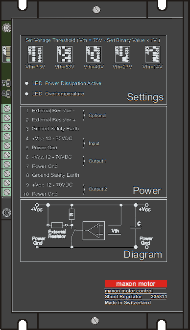
Pin Configuration and Descriptions
| Pin Number | Pin Name | Description |
|---|---|---|
| 1 | V+ (Input) | Positive voltage input to the shunt regulator. |
| 2 | GND | Ground connection for the regulator. |
| 3 | V- (Output) | Regulated voltage output or shunt current path. |
Usage Instructions
How to Use the Component in a Circuit
Connect the Input Voltage (V+):
Attach the positive voltage source to the V+ pin. Ensure the input voltage does not exceed the maximum rating of 70 V.Connect the Ground (GND):
Connect the GND pin to the circuit's ground to complete the electrical path.Connect the Load to V- (Output):
Attach the load to the V- pin. The shunt regulator will maintain a stable voltage across the load by diverting excess current.Heat Dissipation:
Ensure proper heat dissipation by mounting the regulator on a heat sink or using adequate ventilation. This is critical for high-current applications.
Important Considerations and Best Practices
- Input Voltage: Always ensure the input voltage is within the specified range (0–70 V). Exceeding this range may damage the component.
- Current Handling: The regulator can handle a maximum shunt current of 30 A. Use appropriate wiring and connectors to handle high currents safely.
- Thermal Management: For applications with high power dissipation, use a heat sink or thermal paste to prevent overheating.
- Circuit Protection: Consider adding a fuse or circuit breaker to protect the regulator and connected components from overcurrent conditions.
Example: Using the Maxon DSR 70/30 with an Arduino UNO
The Maxon DSR 70/30 can be used to stabilize the voltage supplied to an Arduino UNO in a noisy power environment. Below is an example circuit and code to monitor the regulated voltage:
Circuit Setup
- Connect the V+ pin of the DSR 70/30 to the power supply (e.g., 12 V).
- Connect the GND pin to the Arduino's GND.
- Connect the V- pin to the Arduino's analog input (e.g., A0) to monitor the regulated voltage.
Arduino Code
// Arduino code to monitor the regulated voltage from the Maxon DSR 70/30
const int voltagePin = A0; // Analog pin connected to V- of the shunt regulator
float voltage = 0.0;

void setup() {
  Serial.begin(9600); // Initialize serial communication
  pinMode(voltagePin, INPUT); // Set the pin as input
}

void loop() {
  int sensorValue = analogRead(voltagePin); // Read the analog value
  voltage = (sensorValue * 5.0) / 1023.0; // Convert to voltage (assuming 5V reference)

  // Print the voltage to the Serial Monitor
  Serial.print("Regulated Voltage: ");
  Serial.print(voltage);
  Serial.println(" V");

  delay(1000); // Wait for 1 second before the next reading
}
Troubleshooting and FAQs
Common Issues and Solutions
| Issue | Possible Cause | Solution |
|---|---|---|
| Regulator overheating | Excessive current or poor heat dissipation | Use a heat sink or improve ventilation. |
| Unstable output voltage | Input voltage fluctuations or noise | Add a capacitor across the input terminals. |
| No output voltage | Incorrect wiring or damaged component | Verify connections and check for damage. |
| Arduino reads incorrect voltage | Incorrect analog reference or scaling | Ensure proper reference voltage is set. |
FAQs
Can the Maxon DSR 70/30 handle AC input?
No, the regulator is designed for DC input only. Use a rectifier circuit if AC input is required.What is the maximum power dissipation?
The typical power dissipation is 2 W. Ensure proper thermal management for higher loads.Can I use this regulator with a battery-powered system?
Yes, the DSR 70/30 is suitable for battery-powered systems, provided the input voltage is within the specified range.How do I protect the regulator from overcurrent?
Use a fuse or circuit breaker rated for the maximum current (30 A) to protect the regulator and connected components.
By following this documentation, users can effectively integrate the Maxon DSR 70/30 into their circuits for reliable voltage regulation and protection.