
How to Use AS5048 Magnetic Encoder Position Sensor: Examples, Pinouts, and Specs
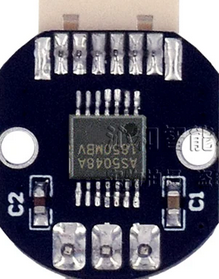
 Design with AS5048 Magnetic Encoder Position Sensor in Cirkit Designer
Introduction
The AS5048 is a high-resolution magnetic rotary encoder designed to provide precise angular position measurements. It operates by detecting the magnetic field of a rotating magnet, making it a non-contact and highly reliable solution for position sensing. With a 14-bit resolution, the AS5048 delivers accurate measurements, making it suitable for applications requiring fine angular precision. It supports both I2C and SPI communication interfaces, ensuring seamless integration into a wide range of systems.
Explore Projects Built with AS5048 Magnetic Encoder Position Sensor
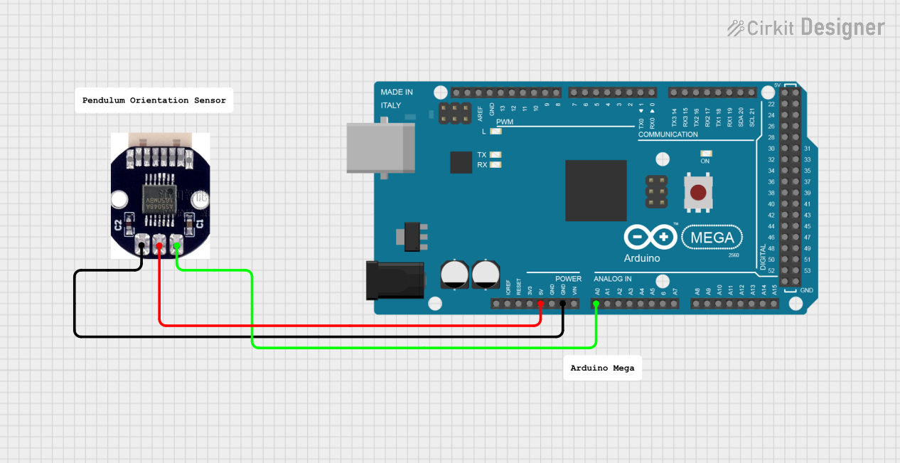 Open Project in Cirkit Designer
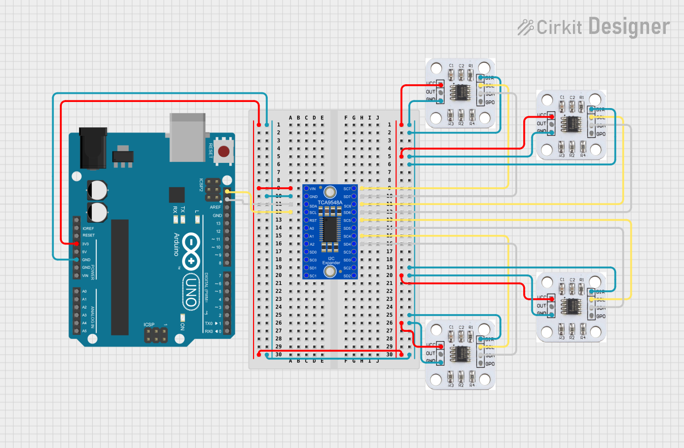 Open Project in Cirkit Designer
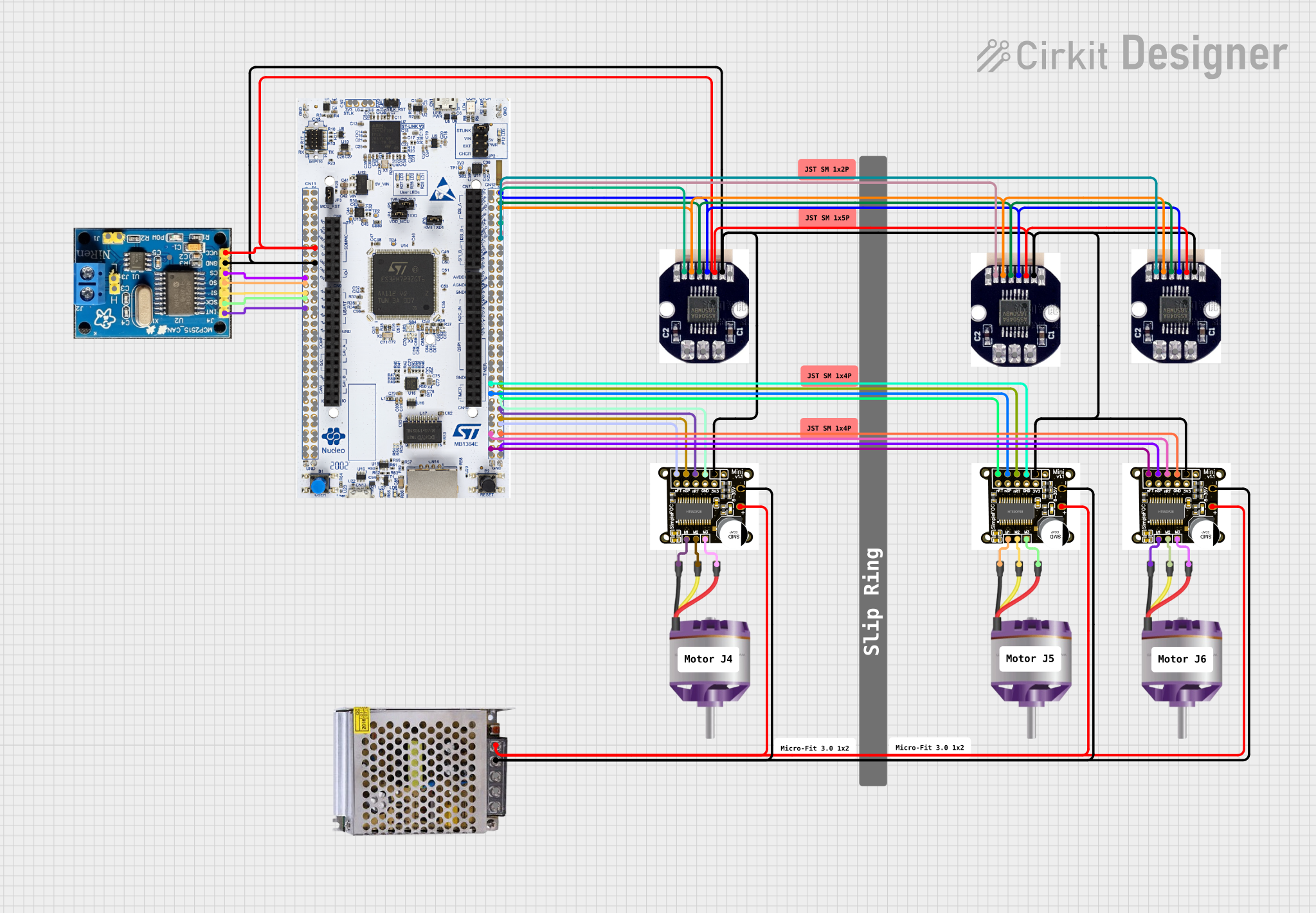 Open Project in Cirkit Designer
 Open Project in Cirkit Designer
Explore Projects Built with AS5048 Magnetic Encoder Position Sensor
Open Project in Cirkit DesignerOpen Project in Cirkit DesignerOpen Project in Cirkit DesignerOpen Project in Cirkit DesignerCommon Applications and Use Cases
- Robotics: Joint position sensing and motor control
- Industrial automation: Rotary position feedback for machinery
- Automotive: Steering angle and throttle position sensing
- Consumer electronics: Joystick and knob position detection
- Medical devices: Precision motion control
Technical Specifications
Key Technical Details
| Parameter | Value |
|---|---|
| Resolution | 14-bit (16,384 positions per revolution) |
| Interface | I2C and SPI |
| Supply Voltage | 3.3V to 5.5V |
| Operating Current | 12 mA (typical) |
| Maximum Speed | 30,000 RPM |
| Operating Temperature | -40°C to +150°C |
| Magnetic Field Strength | 30 mT to 70 mT |
| Output Modes | Absolute position, PWM output |
Pin Configuration and Descriptions
AS5048 Pinout (SPI Mode)
| Pin Name | Pin Number | Description |
|---|---|---|
| VDD | 1 | Power supply (3.3V to 5.5V) |
| GND | 2 | Ground |
| CS | 3 | Chip Select (active low) |
| CLK | 4 | Serial Clock Input |
| MISO | 5 | Master In Slave Out (data output) |
| MOSI | 6 | Master Out Slave In (data input) |
| NC | 7 | Not connected |
| NC | 8 | Not connected |
AS5048 Pinout (I2C Mode)
| Pin Name | Pin Number | Description |
|---|---|---|
| VDD | 1 | Power supply (3.3V to 5.5V) |
| GND | 2 | Ground |
| SDA | 3 | Serial Data Line |
| SCL | 4 | Serial Clock Line |
| NC | 5 | Not connected |
| NC | 6 | Not connected |
| NC | 7 | Not connected |
| NC | 8 | Not connected |
Usage Instructions
How to Use the AS5048 in a Circuit
- Power Supply: Connect the VDD pin to a 3.3V or 5V power source and the GND pin to ground.
- Communication Interface: Choose between SPI or I2C based on your application:
- For SPI, connect the CS, CLK, MISO, and MOSI pins to the corresponding pins on your microcontroller.
- For I2C, connect the SDA and SCL pins to the microcontroller's I2C bus.
- Magnet Placement: Place a diametrically magnetized magnet above the AS5048 sensor. Ensure the magnet is centered and within the recommended distance (1-2 mm) for optimal performance.
- Pull-Up Resistors: For I2C mode, use pull-up resistors (typically 4.7 kΩ) on the SDA and SCL lines.
Important Considerations and Best Practices
- Magnet Alignment: Ensure the magnet is properly aligned with the center of the sensor for accurate readings.
- Magnetic Field Strength: Use a magnet with a field strength between 30 mT and 70 mT.
- Decoupling Capacitor: Place a 100 nF capacitor close to the VDD and GND pins to reduce noise.
- Communication Protocol: Configure your microcontroller to match the AS5048's communication settings (e.g., SPI clock polarity and phase).
Example Code for Arduino UNO (SPI Mode)
#include <SPI.h>

// Define SPI pins for AS5048
const int CS_PIN = 10; // Chip Select pin

void setup() {
  // Initialize serial communication for debugging
  Serial.begin(9600);

  // Configure the Chip Select pin as output
  pinMode(CS_PIN, OUTPUT);
  digitalWrite(CS_PIN, HIGH); // Set CS high to deselect the sensor

  // Initialize SPI communication
  SPI.begin();
  SPI.setClockDivider(SPI_CLOCK_DIV16); // Set SPI clock speed
  SPI.setDataMode(SPI_MODE1); // Clock polarity and phase
}

uint16_t readAS5048() {
  uint16_t angle = 0;

  // Select the AS5048 by setting CS low
  digitalWrite(CS_PIN, LOW);

  // Send a read command (0xFFFF) and receive the response
  uint8_t highByte = SPI.transfer(0xFF); // Send first byte
  uint8_t lowByte = SPI.transfer(0xFF);  // Send second byte

  // Deselect the AS5048 by setting CS high
  digitalWrite(CS_PIN, HIGH);

  // Combine the two bytes into a 14-bit angle value
  angle = ((highByte << 8) | lowByte) & 0x3FFF;

  return angle;
}

void loop() {
  // Read the angle from the AS5048
  uint16_t angle = readAS5048();

  // Print the angle to the serial monitor
  Serial.print("Angle: ");
  Serial.println(angle);

  delay(100); // Wait 100 ms before the next reading
}
Troubleshooting and FAQs
Common Issues and Solutions
No Output or Incorrect Readings:
- Verify the power supply voltage (3.3V to 5.5V).
- Check the magnet alignment and distance from the sensor.
- Ensure proper connections for the selected communication interface (SPI or I2C).
Communication Errors:
- For SPI, confirm the clock polarity and phase settings (SPI_MODE1).
- For I2C, ensure pull-up resistors are present on the SDA and SCL lines.
Unstable Readings:
- Add a decoupling capacitor (100 nF) near the VDD and GND pins.
- Use a stable power supply to minimize noise.
FAQs
Q: Can the AS5048 measure absolute position?
A: Yes, the AS5048 provides absolute angular position measurements with 14-bit resolution.
Q: What type of magnet should I use?
A: Use a diametrically magnetized magnet with a field strength of 30 mT to 70 mT.
Q: Can I use the AS5048 with a 3.3V microcontroller?
A: Yes, the AS5048 operates with a supply voltage range of 3.3V to 5.5V, making it compatible with 3.3V systems.
Q: How fast can the AS5048 operate?
A: The AS5048 supports rotational speeds of up to 30,000 RPM.