
How to Use PAM8403: Examples, Pinouts, and Specs
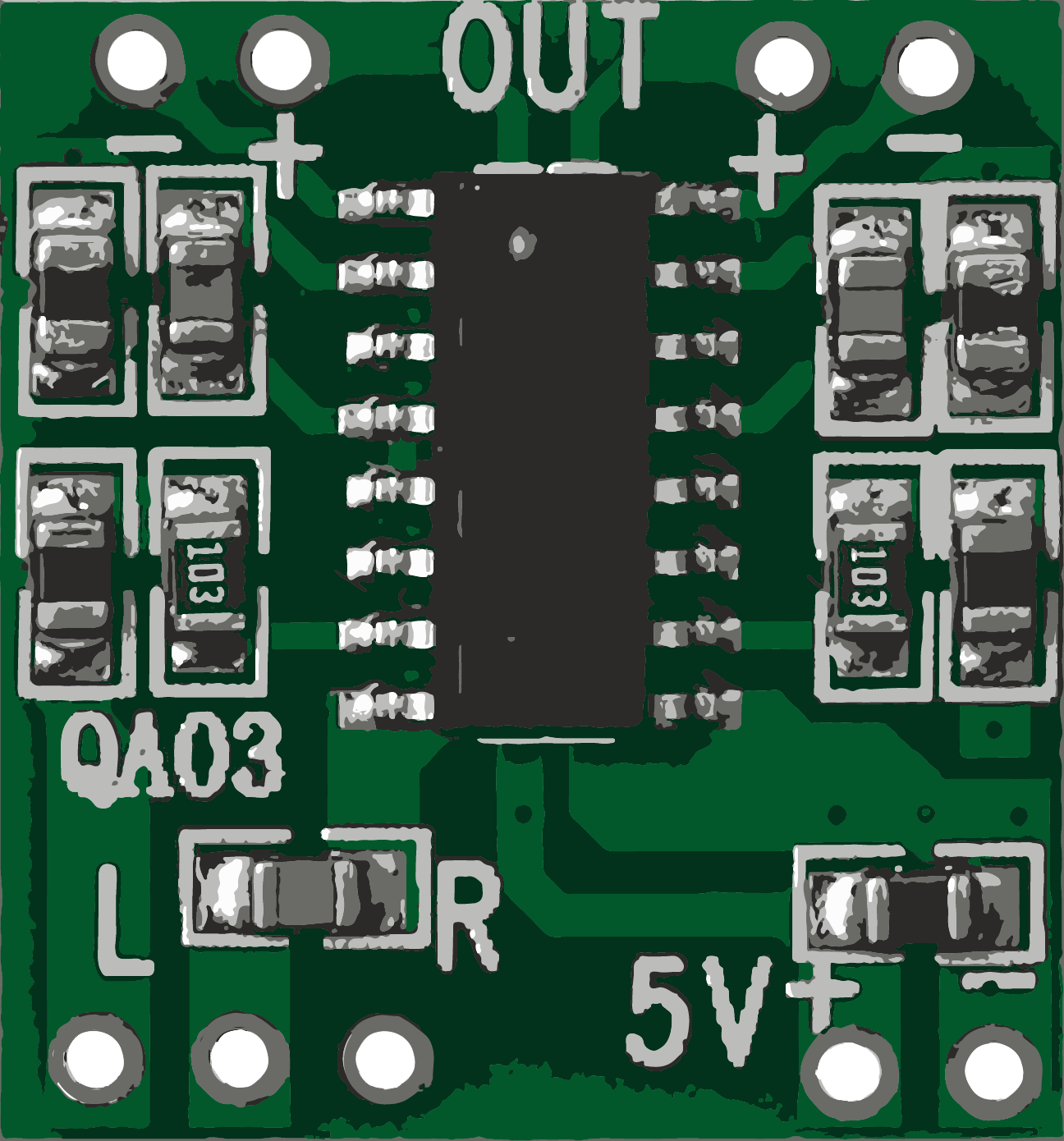
 Design with PAM8403 in Cirkit Designer
Introduction
The PAM8403 is a low-power, class D audio amplifier designed for high efficiency and low distortion. It is widely used in portable audio applications due to its compact size, low power consumption, and ability to deliver high-quality sound. The PAM8403 can drive stereo speakers with an output power of up to 3W per channel, making it suitable for battery-powered devices and small audio systems. Its wide operating voltage range and minimal external components make it easy to integrate into various designs.
Explore Projects Built with PAM8403
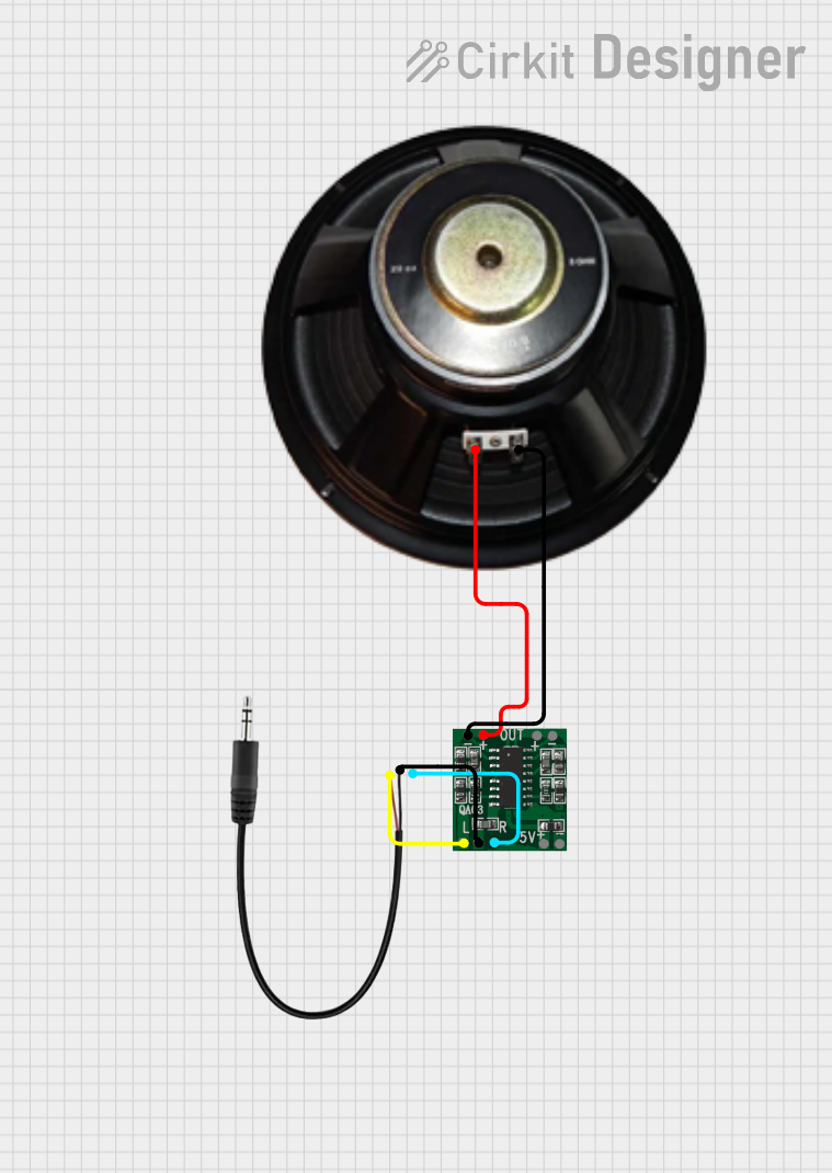 Open Project in Cirkit Designer
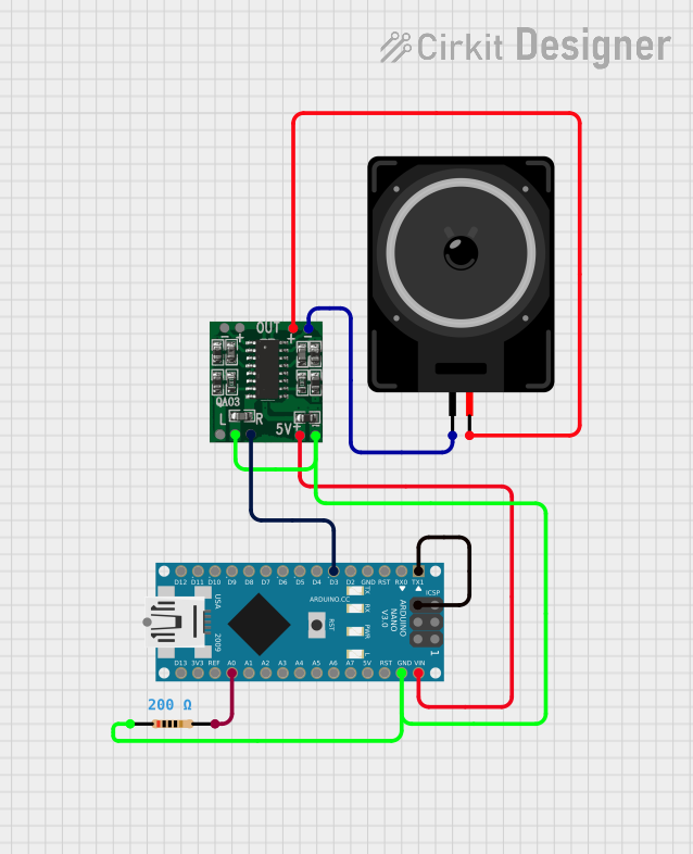 Open Project in Cirkit Designer
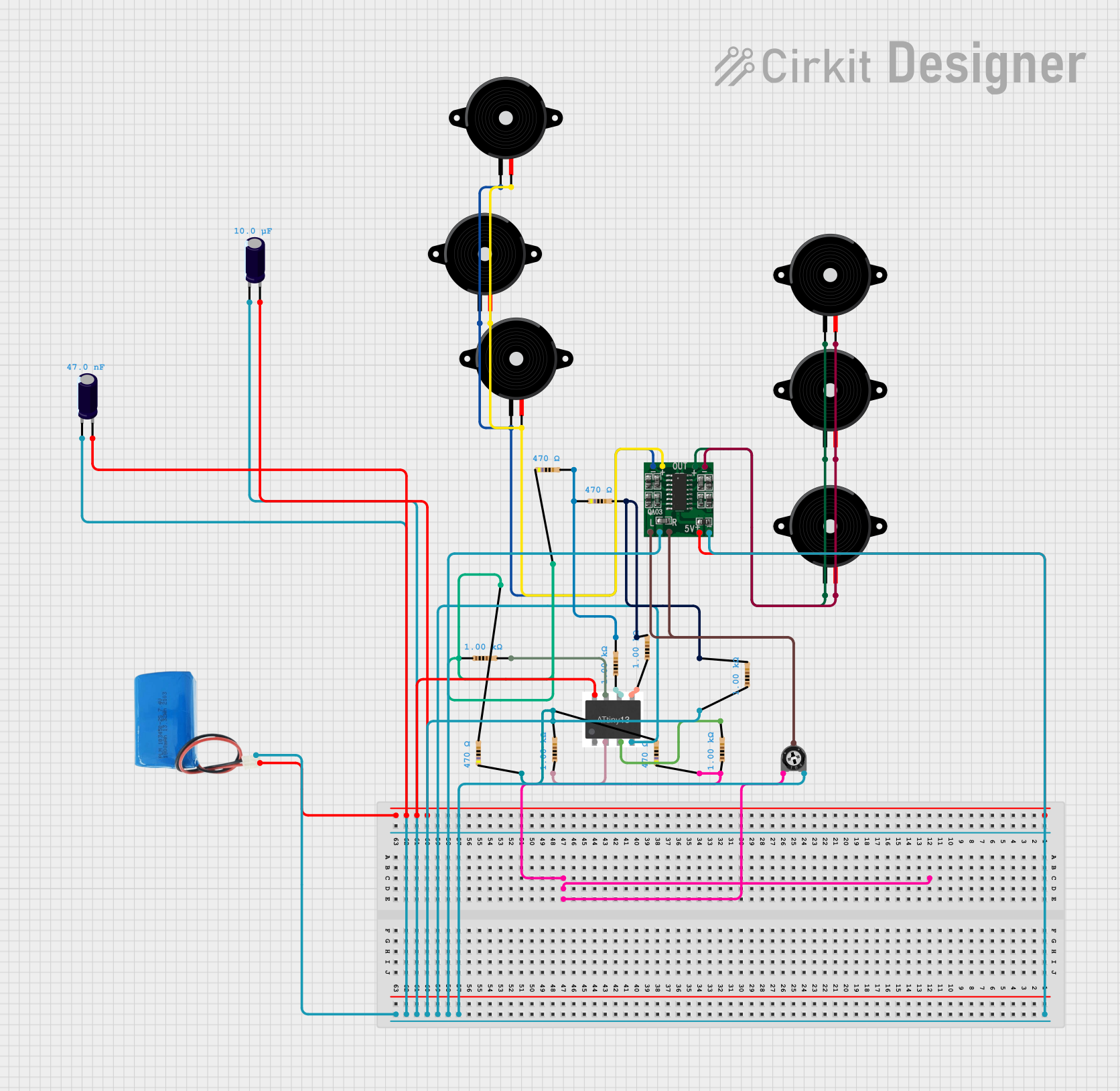 Open Project in Cirkit Designer
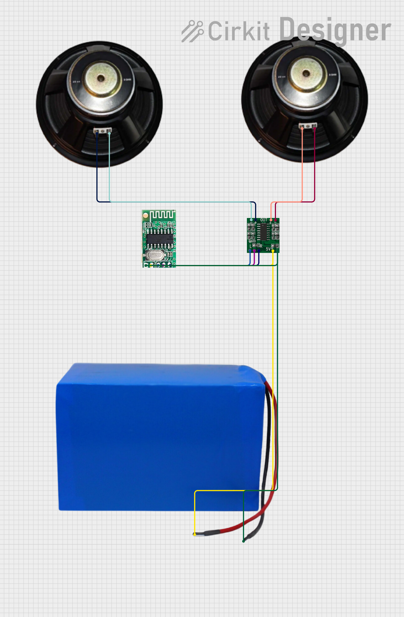 Open Project in Cirkit Designer
Explore Projects Built with PAM8403
Open Project in Cirkit DesignerOpen Project in Cirkit DesignerOpen Project in Cirkit DesignerOpen Project in Cirkit DesignerCommon Applications
- Portable speakers
- DIY audio projects
- Battery-powered audio systems
- Embedded audio solutions
- Audio amplifiers for small devices
Technical Specifications
Key Specifications
| Parameter | Value |
|---|---|
| Operating Voltage Range | 2.5V to 5.5V |
| Output Power | 3W per channel (at 4Ω, 5V) |
| Efficiency | Up to 90% |
| Total Harmonic Distortion (THD) | < 0.1% (at 1W, 4Ω, 5V) |
| Signal-to-Noise Ratio | 85 dB |
| Channel Configuration | Stereo (2 channels) |
| Input Impedance | 15 kΩ |
| Shutdown Current | < 1 µA |
Pin Configuration and Descriptions
The PAM8403 is typically available in an 8-pin SOP package. Below is the pinout and description:
| Pin Number | Pin Name | Description |
|---|---|---|
| 1 | INL | Left channel audio input |
| 2 | INR | Right channel audio input |
| 3 | SVCC | Supply voltage for the amplifier |
| 4 | GND | Ground |
| 5 | OUTR | Right channel audio output |
| 6 | OUTR- | Negative terminal for right channel output |
| 7 | OUTL- | Negative terminal for left channel output |
| 8 | OUTL | Left channel audio output |
Usage Instructions
How to Use the PAM8403 in a Circuit
- Power Supply: Connect a DC power supply (2.5V to 5.5V) to the
SVCCpin and ground to theGNDpin. A 5V supply is recommended for optimal performance. - Audio Input: Connect the left and right audio signals to the
INLandINRpins, respectively. Use decoupling capacitors (e.g., 1 µF) in series with the input signals to block DC offset. - Speaker Connection: Connect the left and right speakers to the
OUTL,OUTL-,OUTR, andOUTR-pins. Ensure the speakers have an impedance of 4Ω or 8Ω for proper operation. - Bypass Capacitor: Place a bypass capacitor (e.g., 0.1 µF) close to the
SVCCpin to stabilize the power supply. - Shutdown Mode: To enable shutdown mode, pull the
SVCCpin to ground through a resistor. This reduces power consumption when the amplifier is not in use.
Important Considerations
- Speaker Impedance: Use speakers with an impedance of 4Ω or 8Ω for optimal performance.
- Power Supply: Ensure the power supply voltage does not exceed 5.5V to avoid damaging the IC.
- Heat Dissipation: The PAM8403 is highly efficient, but ensure proper ventilation to avoid overheating in high-power applications.
- Noise Reduction: Use proper grounding and shielding techniques to minimize noise and interference.
Example: Connecting PAM8403 to an Arduino UNO
The PAM8403 can be used with an Arduino UNO to amplify audio signals. Below is an example of how to generate a simple tone using the Arduino and output it through the PAM8403.
Circuit Connections
- Connect the
INLpin of the PAM8403 to Arduino pin9(PWM output). - Connect the
INRpin of the PAM8403 to Arduino pin10(PWM output). - Connect the
SVCCpin to a 5V power supply and theGNDpin to ground. - Connect speakers to the
OUTL,OUTL-,OUTR, andOUTR-pins.
Arduino Code
// PAM8403 Example: Generate a tone using Arduino PWM
// Connect INL to pin 9 and INR to pin 10 of the Arduino UNO

void setup() {
  pinMode(9, OUTPUT);  // Set pin 9 as output for left channel
  pinMode(10, OUTPUT); // Set pin 10 as output for right channel
}

void loop() {
  // Generate a 1 kHz tone on the left channel
  analogWrite(9, 128); // 50% duty cycle for PWM signal
  delayMicroseconds(500); // 1 kHz frequency (1/1000 seconds)

  // Generate a 1 kHz tone on the right channel
  analogWrite(10, 128); // 50% duty cycle for PWM signal
  delayMicroseconds(500); // 1 kHz frequency (1/1000 seconds)
}
Troubleshooting and FAQs
Common Issues
No Sound Output:
- Check the power supply voltage and ensure it is within the 2.5V to 5.5V range.
- Verify that the audio input signals are connected correctly to the
INLandINRpins. - Ensure the speakers are properly connected to the output pins.
Distorted Audio:
- Ensure the input signal amplitude does not exceed the maximum input range.
- Check the speaker impedance; it should be 4Ω or 8Ω.
- Verify that the power supply can provide sufficient current for the amplifier.
Overheating:
- Ensure proper ventilation around the PAM8403.
- Check for short circuits in the speaker connections.
FAQs
Q1: Can I use the PAM8403 with a 3.7V lithium-ion battery?
A1: Yes, the PAM8403 can operate with a 3.7V lithium-ion battery as it supports a voltage range of 2.5V to 5.5V.
Q2: What is the maximum speaker power I can use with the PAM8403?
A2: The PAM8403 can drive speakers with up to 3W per channel at 4Ω impedance and 5V supply.
Q3: Can I use the PAM8403 for mono audio applications?
A3: Yes, you can use only one channel (left or right) for mono audio applications. Leave the unused input and output pins unconnected.
Q4: How can I reduce noise in my circuit?
A4: Use decoupling capacitors on the power supply and input lines, and ensure proper grounding to minimize noise.