How to Use lcd 20*4: Examples, Pinouts, and Specs
Introduction
The 20x4 LCD (Liquid Crystal Display) is a versatile display module capable of showing 20 characters per line across 4 lines, making it ideal for applications requiring a clear and concise text display. It is widely used in embedded systems, microcontroller projects, and industrial control systems. The module operates using either a parallel or serial interface, providing flexibility in integration with various systems.
Explore Projects Built with lcd 20*4

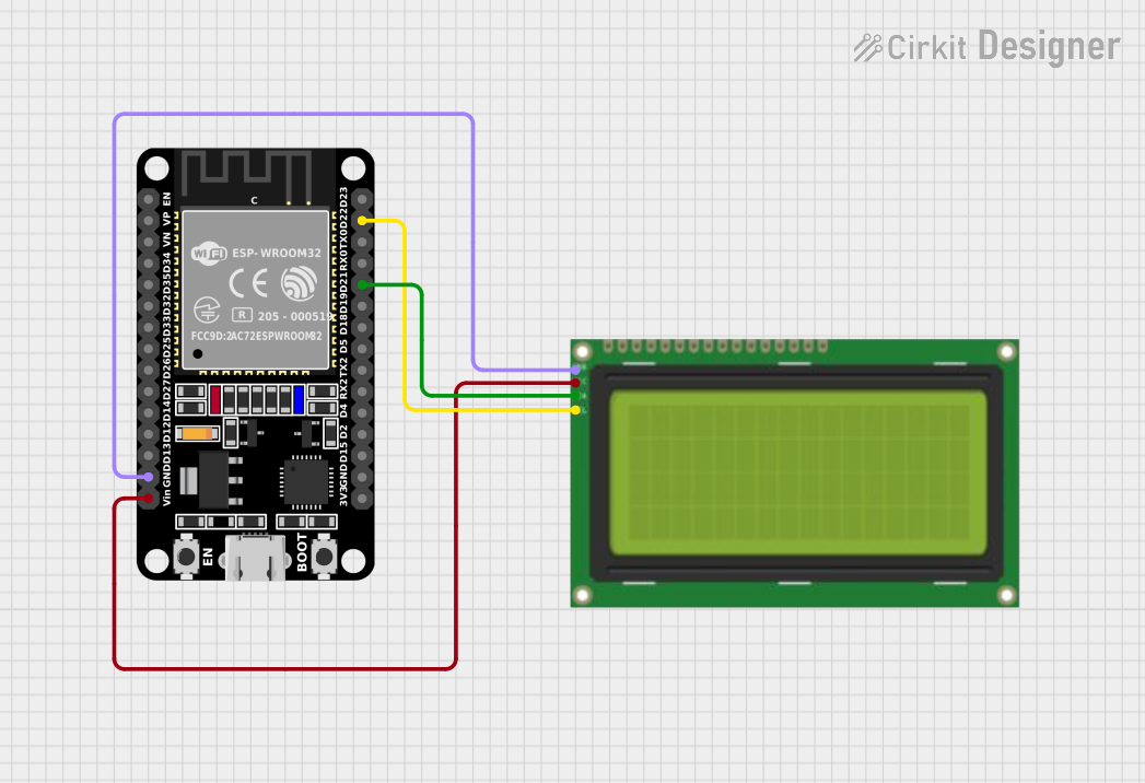
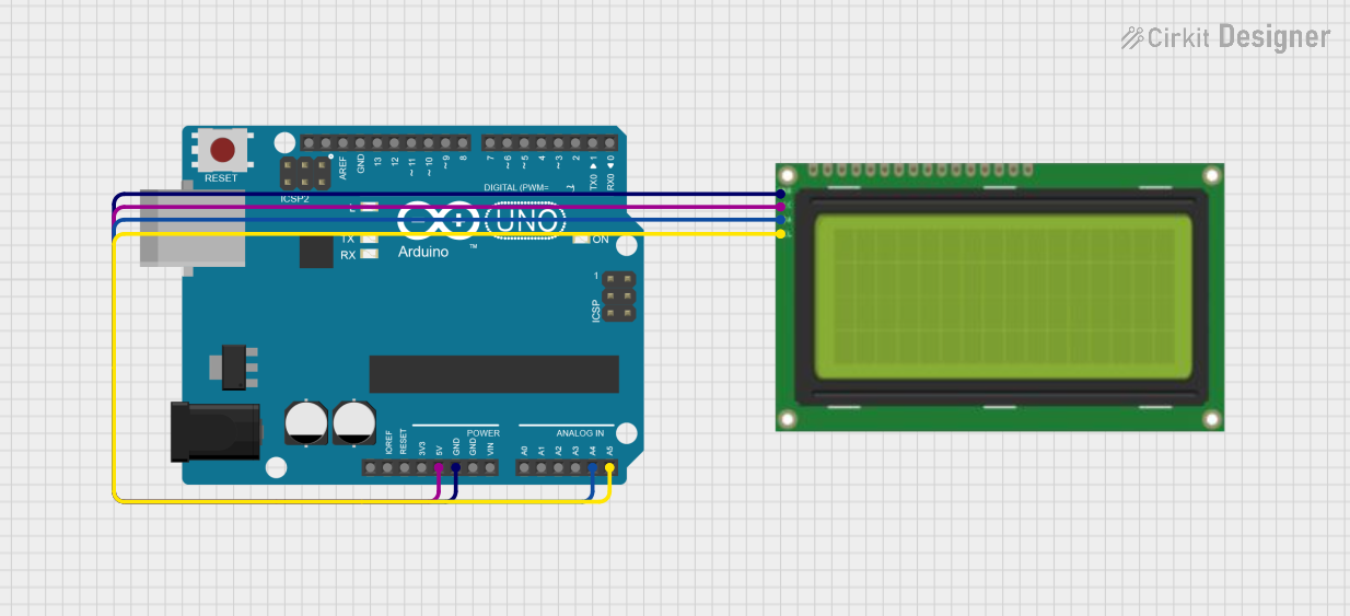
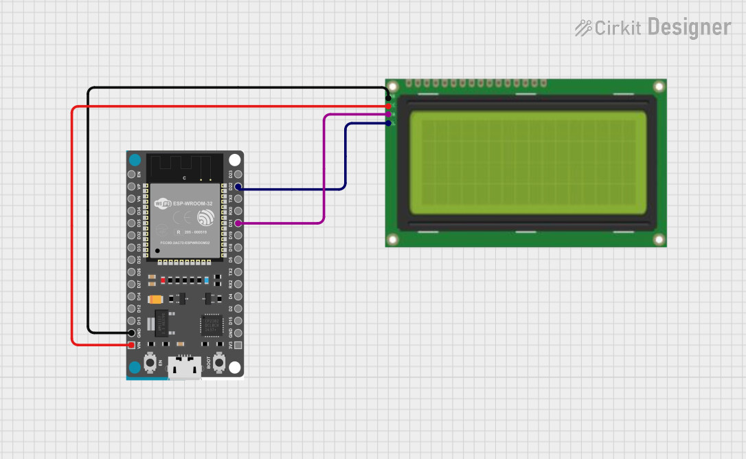
Explore Projects Built with lcd 20*4
Common Applications
- Embedded systems and microcontroller projects
- Industrial control panels
- Home automation systems
- Measurement and monitoring devices
- Educational and prototyping projects
Technical Specifications
The following table outlines the key technical details of the LCD 20x4 module:
| Parameter | Specification |
|---|---|
| Display Type | 20 characters x 4 lines |
| Operating Voltage | 4.7V to 5.3V |
| Operating Current | 1.5mA (without backlight) |
| Backlight Voltage | 4.2V to 4.6V |
| Backlight Current | 120mA (typical) |
| Interface Type | Parallel (4-bit or 8-bit) or I2C |
| Character Size | 5x8 dot matrix |
| Operating Temperature | -20°C to +70°C |
| Storage Temperature | -30°C to +80°C |
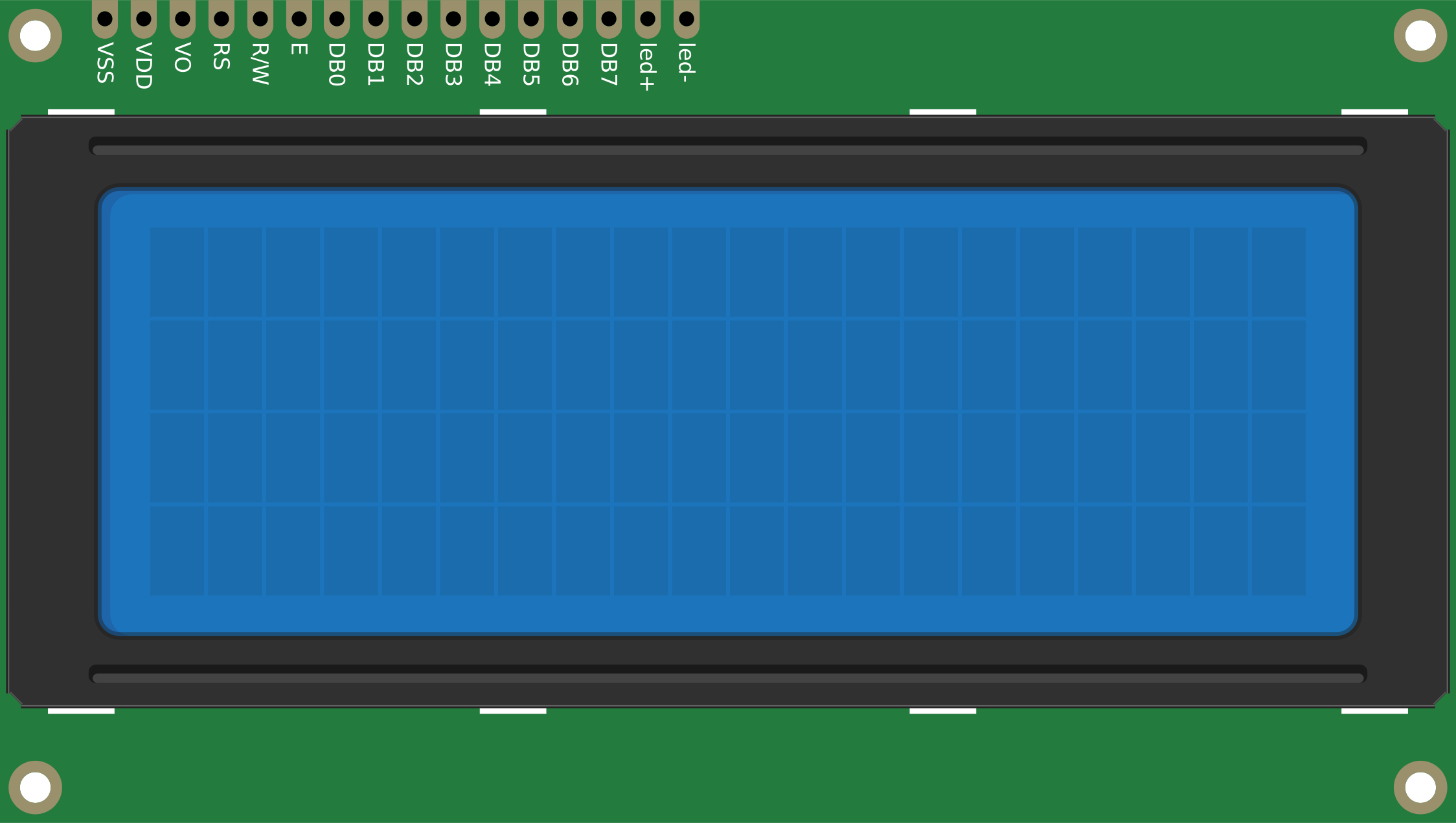
Pin Configuration (Parallel Interface)
The LCD 20x4 module typically has 16 pins when using the parallel interface. The pin descriptions are as follows:
| Pin | Name | Description |
|---|---|---|
| 1 | VSS | Ground (0V) |
| 2 | VDD | Power supply (4.7V to 5.3V) |
| 3 | VO | Contrast adjustment (connect to a potentiometer) |
| 4 | RS | Register Select (0: Command, 1: Data) |
| 5 | RW | Read/Write (0: Write, 1: Read) |
| 6 | E | Enable signal (triggers data read/write) |
| 7-14 | D0-D7 | Data bus lines (D0-D3 used in 8-bit mode, D4-D7 used in 4-bit mode) |
| 15 | A | Backlight anode (+) |
| 16 | K | Backlight cathode (-) |
Pin Configuration (I2C Interface)
When using an I2C adapter, the module typically has 4 pins:
| Pin | Name | Description |
|---|---|---|
| 1 | GND | Ground (0V) |
| 2 | VCC | Power supply (4.7V to 5.3V) |
| 3 | SDA | Serial Data Line |
| 4 | SCL | Serial Clock Line |
Usage Instructions
Connecting the LCD 20x4 to an Arduino UNO (I2C Interface)
Using an I2C adapter simplifies the wiring and reduces the number of pins required. Follow these steps to connect and use the LCD 20x4 with an Arduino UNO:
Wiring:
- Connect the
GNDpin of the LCD to theGNDpin on the Arduino. - Connect the
VCCpin of the LCD to the5Vpin on the Arduino. - Connect the
SDApin of the LCD to theA4pin on the Arduino. - Connect the
SCLpin of the LCD to theA5pin on the Arduino.
- Connect the
Install the Required Library:
- Open the Arduino IDE.
- Go to
Sketch>Include Library>Manage Libraries. - Search for
LiquidCrystal_I2Cand install the library.
Example Code: Use the following code to display text on the LCD:
// Include the LiquidCrystal_I2C library
#include <Wire.h>
#include <LiquidCrystal_I2C.h>

// Initialize the LCD with I2C address 0x27 and dimensions 20x4
LiquidCrystal_I2C lcd(0x27, 20, 4);

void setup() {
  // Initialize the LCD
  lcd.begin();

  // Turn on the backlight
  lcd.backlight();

  // Display a message on the LCD
  lcd.setCursor(0, 0); // Set cursor to column 0, row 0
  lcd.print("Hello, World!");
  lcd.setCursor(0, 1); // Set cursor to column 0, row 1
  lcd.print("LCD 20x4 Demo");
}

void loop() {
  // No actions in the loop for this example
}
Important Considerations
- Contrast Adjustment: Use a 10kΩ potentiometer connected to the
VOpin to adjust the display contrast. - Backlight Control: If the backlight is too bright, you can add a resistor (e.g., 220Ω) in series with the backlight pins.
- I2C Address: The default I2C address is usually
0x27, but it may vary depending on the adapter. Use an I2C scanner sketch to determine the correct address if needed.
Troubleshooting and FAQs
Common Issues and Solutions
No Display on the LCD:
- Ensure the power connections (
VDDandGND) are correct. - Adjust the contrast using the potentiometer connected to the
VOpin. - Verify the I2C address if using the I2C interface.
- Ensure the power connections (
Flickering or Unstable Display:
- Check the connections for loose wires or poor soldering.
- Ensure the power supply provides sufficient current for the LCD and backlight.
Incorrect or Garbled Characters:
- Verify the data connections (
D4-D7for 4-bit mode orD0-D7for 8-bit mode). - Ensure the correct library and initialization settings are used in the code.
- Verify the data connections (
Backlight Not Working:
- Check the backlight pins (
AandK) for proper connections. - Ensure the backlight voltage is within the specified range.
- Check the backlight pins (
FAQs
Q: Can I use the LCD 20x4 with a 3.3V microcontroller?
A: The LCD 20x4 is designed for 5V operation. To use it with a 3.3V microcontroller, you will need a level shifter or a 5V power source for the LCD.
Q: How do I find the I2C address of my LCD?
A: Use an I2C scanner sketch available in the Arduino IDE examples to detect the address of your LCD module.
Q: Can I display custom characters on the LCD?
A: Yes, the LCD supports custom characters. You can define them using the createChar() function in the LiquidCrystal library.
Q: What is the maximum viewing angle of the LCD?
A: The typical viewing angle is around 45° to 60°, depending on the specific module.
By following this documentation, you can effectively integrate and troubleshoot the LCD 20x4 module in your projects.