How to Use MSP432P4111: Examples, Pinouts, and Specs
Introduction
The MSP432P4111 is a low-power microcontroller developed by Texas Instruments. It is built around a 32-bit ARM Cortex-M4F core, which includes a floating-point unit (FPU) for efficient mathematical computations. This microcontroller is designed for high-performance applications while maintaining low energy consumption, making it ideal for battery-powered and energy-sensitive devices.
Explore Projects Built with MSP432P4111


Explore Projects Built with MSP432P4111
Common Applications and Use Cases
- Industrial automation and control systems
- Wearable devices and IoT applications
- Data acquisition and signal processing
- Low-power sensor nodes
- Consumer electronics requiring efficient computation and low power
Technical Specifications
Key Technical Details
| Parameter | Specification |
|---|---|
| Core Architecture | ARM Cortex-M4F (32-bit) |
| Operating Voltage | 1.62V to 3.7V |
| Maximum Clock Frequency | 48 MHz |
| Flash Memory | 256 KB |
| SRAM | 64 KB |
| GPIO Pins | Up to 84 |
| ADC | 14-bit, up to 16 channels |
| Timers | 4 x 16-bit timers, 2 x 32-bit timers |
| Communication Interfaces | UART, SPI, I2C, eUSCI modules |
| Low-Power Modes | 5 low-power modes with active power < 95 µA/MHz |
| Operating Temperature Range | -40°C to 85°C |
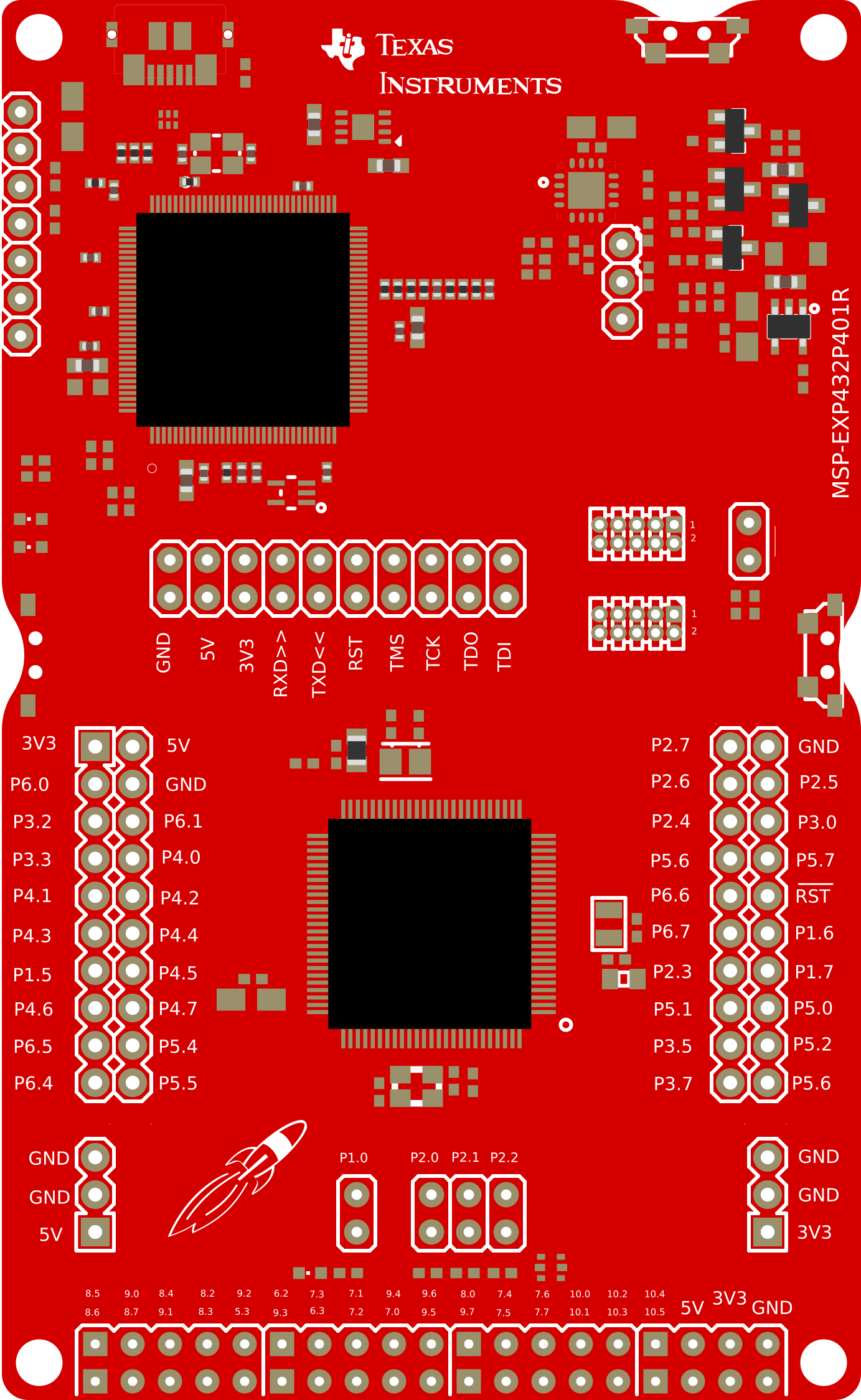
Pin Configuration and Descriptions
The MSP432P4111 is available in a 100-pin LQFP package. Below is a summary of key pins:
| Pin Name | Pin Number | Description |
|---|---|---|
| VCC | Multiple | Power supply pins (1.62V to 3.7V) |
| GND | Multiple | Ground pins |
| GPIO | Multiple | General-purpose input/output pins |
| ADC_INx | Multiple | Analog input pins for ADC |
| UART_TX | Configurable | UART transmit pin |
| UART_RX | Configurable | UART receive pin |
| SPI_MOSI | Configurable | SPI Master Out Slave In |
| SPI_MISO | Configurable | SPI Master In Slave Out |
| I2C_SCL | Configurable | I2C clock line |
| I2C_SDA | Configurable | I2C data line |
| RESET | Dedicated | Reset pin |
| XTAL_IN | Dedicated | External crystal oscillator input |
| XTAL_OUT | Dedicated | External crystal oscillator output |
Refer to the official datasheet for a complete pinout and alternate functions.
Usage Instructions
How to Use the MSP432P4111 in a Circuit
- Power Supply: Ensure the microcontroller is powered within the operating voltage range (1.62V to 3.7V). Use decoupling capacitors (e.g., 0.1 µF) near the VCC and GND pins to stabilize the power supply.
- Clock Configuration: The MSP432P4111 can use an internal clock or an external crystal oscillator. For precise timing, connect a crystal oscillator to the XTAL_IN and XTAL_OUT pins.
- Programming: Use the JTAG or SWD interface to program the microcontroller. Texas Instruments provides the Code Composer Studio (CCS) IDE for development.
- Peripherals: Configure peripherals (e.g., ADC, UART, SPI) using the driver library provided by Texas Instruments or through direct register manipulation.
- Low-Power Modes: Utilize the low-power modes to reduce energy consumption when the microcontroller is idle.
Important Considerations and Best Practices
- GPIO Configuration: Set unused GPIO pins to a low-power state to minimize current leakage.
- Debugging: Use the EnergyTrace tool in CCS to monitor power consumption during development.
- External Pull-Up/Down Resistors: For pins that require a defined state, use external pull-up or pull-down resistors.
- Bypass Capacitors: Place bypass capacitors close to the power pins to reduce noise and improve stability.
Example: Interfacing MSP432P4111 with Arduino UNO
Below is an example of using the MSP432P4111 to read an analog signal and send the data to an Arduino UNO via UART.
Circuit Connections
- Connect the MSP432P4111's UART_TX pin to the Arduino UNO's RX pin.
- Connect the MSP432P4111's UART_RX pin to the Arduino UNO's TX pin.
- Connect the GND pins of both devices.
Code for MSP432P4111
#include "driverlib.h"

// UART configuration parameters
const eUSCI_UART_Config uartConfig = {
    EUSCI_A_UART_CLOCKSOURCE_SMCLK, // Clock source
    78,                             // Clock prescaler
    2,                              // First mod register
    0,                              // Second mod register
    EUSCI_A_UART_NO_PARITY,         // No parity
    EUSCI_A_UART_LSB_FIRST,         // LSB first
    EUSCI_A_UART_ONE_STOP_BIT,      // One stop bit
    EUSCI_A_UART_MODE,              // UART mode
    EUSCI_A_UART_OVERSAMPLING_BAUDRATE_GENERATION // Oversampling
};

int main(void) {
    WDT_A_holdTimer(); // Stop watchdog timer

    // Configure UART pins
    GPIO_setAsPeripheralModuleFunctionInputPin(GPIO_PORT_P1,
        GPIO_PIN2 | GPIO_PIN3, GPIO_PRIMARY_MODULE_FUNCTION);

    // Initialize UART
    UART_initModule(EUSCI_A0_BASE, &uartConfig);
    UART_enableModule(EUSCI_A0_BASE);

    while (1) {
        // Send a test message
        const char message[] = "Hello from MSP432P4111!\r\n";
        for (int i = 0; i < sizeof(message) - 1; i++) {
            UART_transmitData(EUSCI_A0_BASE, message[i]);
        }
        __delay_cycles(48000000); // Delay for 1 second at 48 MHz
    }
}
Code for Arduino UNO
void setup() {
    Serial.begin(9600); // Initialize UART at 9600 baud
}

void loop() {
    if (Serial.available()) {
        // Read and print data from MSP432P4111
        char received = Serial.read();
        Serial.print(received);
    }
}
Troubleshooting and FAQs
Common Issues and Solutions
Microcontroller Not Powering On
- Ensure the power supply voltage is within the specified range (1.62V to 3.7V).
- Check for proper connections and decoupling capacitors near the VCC and GND pins.
UART Communication Fails
- Verify the baud rate and UART configuration on both devices.
- Check the physical connections between the MSP432P4111 and the other device.
ADC Readings Are Inaccurate
- Ensure the analog input voltage is within the ADC's input range.
- Use a low-pass filter to reduce noise on the analog input signal.
High Power Consumption
- Verify that unused GPIO pins are configured in a low-power state.
- Use low-power modes when the microcontroller is idle.
FAQs
Q: Can the MSP432P4111 operate without an external crystal oscillator?
A: Yes, the MSP432P4111 has an internal clock source, but an external crystal oscillator is recommended for applications requiring precise timing.
Q: What development tools are available for the MSP432P4111?
A: Texas Instruments provides Code Composer Studio (CCS) and the MSP432 Driver Library for development. Additionally, third-party tools like Keil and IAR are supported.
Q: How can I monitor power consumption during development?
A: Use the EnergyTrace tool available in Code Composer Studio to measure and optimize power usage.