How to Use Kipas DC: Examples, Pinouts, and Specs
Introduction
A DC fan, or "Kipas DC," is an electric fan powered by direct current (DC) electricity. It is widely used for cooling and ventilation in electronic devices and systems. DC fans are known for their energy efficiency, compact size, and ability to provide consistent airflow, making them ideal for applications such as computer cooling, power supply ventilation, and industrial equipment.
Explore Projects Built with Kipas DC


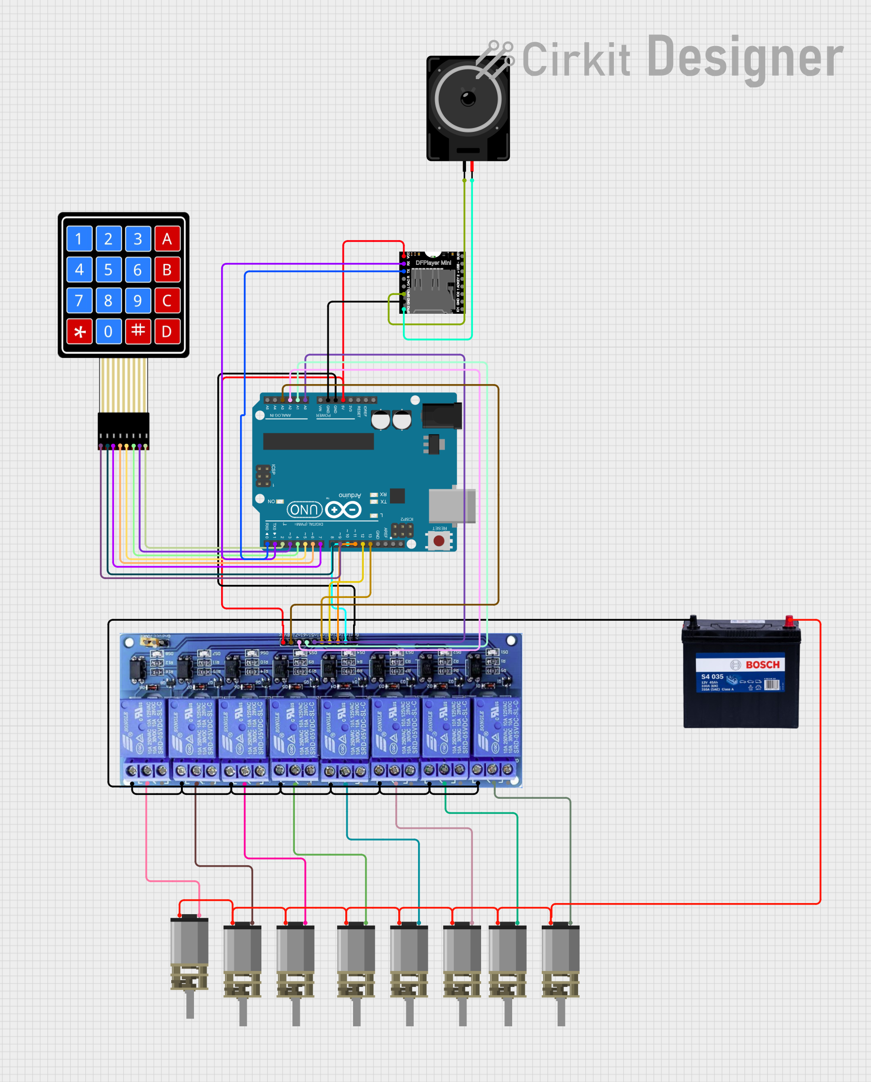

Explore Projects Built with Kipas DC
Common Applications and Use Cases
- Cooling computer processors, graphics cards, and power supplies
- Ventilation in electronic enclosures and cabinets
- Air circulation in small appliances and industrial systems
- Cooling for 3D printers and other hobbyist projects
- Automotive applications, such as cooling car electronics
Technical Specifications
Key Technical Details
- Operating Voltage: Typically 5V, 12V, or 24V DC (varies by model)
- Current Consumption: 0.1A to 1A (depending on size and power rating)
- Power Rating: 0.5W to 10W
- Speed: 1000 to 5000 RPM (Revolutions Per Minute)
- Airflow: 10 to 100 CFM (Cubic Feet per Minute)
- Noise Level: 20 to 40 dBA (varies by model)
- Connector Type: 2-pin, 3-pin, or 4-pin (PWM control available on 4-pin models)
- Lifespan: 30,000 to 70,000 hours (depending on quality and usage)
Pin Configuration and Descriptions
Below is the pin configuration for common DC fan types:
2-Pin DC Fan
| Pin Number | Name | Description |
|---|---|---|
| 1 | VCC | Positive power supply (e.g., 12V DC) |
| 2 | GND | Ground connection |
3-Pin DC Fan
| Pin Number | Name | Description |
|---|---|---|
| 1 | VCC | Positive power supply (e.g., 12V DC) |
| 2 | GND | Ground connection |
| 3 | Tachometer | Outputs fan speed as a pulse signal |
4-Pin DC Fan (PWM Control)
| Pin Number | Name | Description |
|---|---|---|
| 1 | VCC | Positive power supply (e.g., 12V DC) |
| 2 | GND | Ground connection |
| 3 | Tachometer | Outputs fan speed as a pulse signal |
| 4 | PWM | Pulse Width Modulation input for speed control |
Usage Instructions
How to Use the Component in a Circuit
- Power Supply: Ensure the DC fan is powered with the correct voltage (e.g., 5V, 12V, or 24V DC). Exceeding the rated voltage can damage the fan.
- Connections:
- For a 2-pin fan, connect the VCC pin to the positive terminal of the power supply and the GND pin to the negative terminal.
- For a 3-pin or 4-pin fan, connect the additional pins (Tachometer and PWM) as needed for speed monitoring and control.
- Speed Control: If using a 4-pin fan, provide a PWM signal (typically 25 kHz) to the PWM pin to control the fan speed. A duty cycle of 0% stops the fan, while 100% runs it at full speed.
Important Considerations and Best Practices
- Voltage Compatibility: Always check the fan's rated voltage before connecting it to a power source.
- Current Rating: Ensure the power supply can provide sufficient current for the fan's operation.
- Airflow Direction: Most DC fans have an arrow indicating the direction of airflow and blade rotation. Install the fan accordingly.
- Noise Reduction: Use rubber mounts or grommets to minimize vibration and noise.
- Dust and Maintenance: Periodically clean the fan to prevent dust buildup, which can reduce efficiency and lifespan.
Example: Connecting a 12V DC Fan to an Arduino UNO
Below is an example of controlling a 12V DC fan using an Arduino UNO and a transistor for switching:
// Define pin connections
const int fanPin = 9; // PWM pin connected to the transistor base
const int pwmValue = 128; // Set PWM duty cycle (0-255)

// Setup function
void setup() {
  pinMode(fanPin, OUTPUT); // Set fanPin as an output
}

// Loop function
void loop() {
  analogWrite(fanPin, pwmValue); // Control fan speed with PWM
  delay(1000); // Keep fan running for 1 second
}
Note: Use a suitable NPN transistor (e.g., 2N2222) and a base resistor (e.g., 1kΩ) to switch the fan. Connect the fan's VCC to a 12V power supply and its GND to the transistor's collector. The emitter should be connected to the Arduino's GND.
Troubleshooting and FAQs
Common Issues and Solutions
Fan Not Spinning:
- Cause: Incorrect voltage or loose connections.
- Solution: Verify the power supply voltage and ensure all connections are secure.
Fan Spins Slowly:
- Cause: Insufficient current or low PWM duty cycle.
- Solution: Check the power supply's current rating and increase the PWM duty cycle if applicable.
Excessive Noise:
- Cause: Dust buildup or improper mounting.
- Solution: Clean the fan blades and ensure it is securely mounted with vibration-dampening materials.
Fan Overheats or Fails Prematurely:
- Cause: Overvoltage or continuous operation in a dusty environment.
- Solution: Use the fan within its rated voltage and clean it regularly.
FAQs
Q: Can I use a DC fan with an AC power source?
A: No, DC fans require a DC power source. Use an AC-to-DC adapter if needed.Q: How do I determine the airflow direction?
A: Look for the arrow markings on the fan housing, which indicate airflow and blade rotation direction.Q: Can I control a 2-pin fan's speed?
A: Speed control for 2-pin fans is limited. You can use a variable DC power supply or a PWM circuit to adjust the voltage.Q: What is the purpose of the Tachometer pin on a 3-pin fan?
A: The Tachometer pin outputs a pulse signal that represents the fan's speed, which can be monitored by a microcontroller.
By following this documentation, you can effectively use and troubleshoot a DC fan in various applications.