How to Use signal ampifier: Examples, Pinouts, and Specs
Introduction
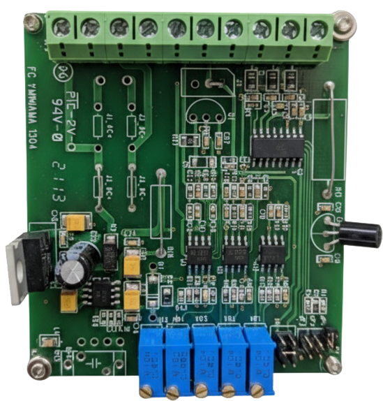
The JS101 Signal Amplifier, manufactured by Jihsense, is an electronic device designed to amplify weak signals by increasing their power, voltage, or current. This component is essential in applications where signal strength needs to be enhanced for better transmission, processing, or reception. It is widely used in audio systems, radio communication, and other electronic systems requiring signal amplification.
Explore Projects Built with signal ampifier
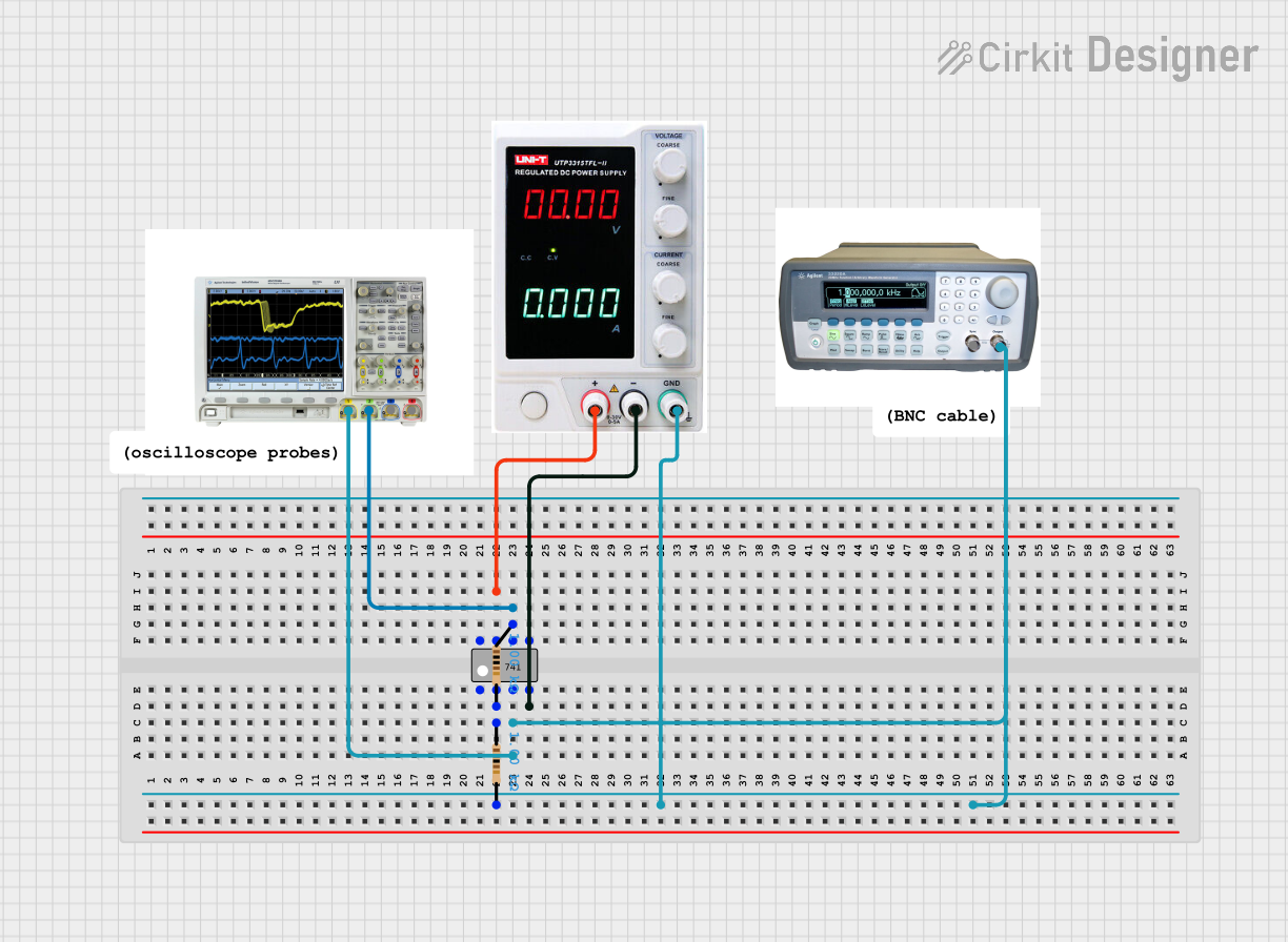

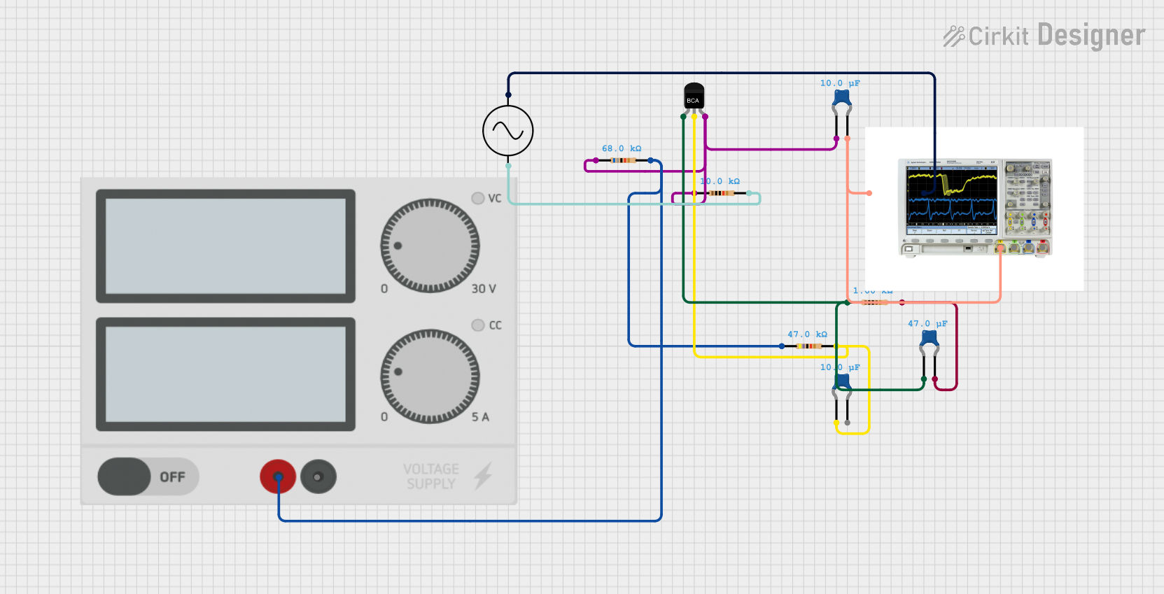

Explore Projects Built with signal ampifier
Common Applications and Use Cases
- Audio Systems: Amplifying audio signals for speakers or headphones.
- Radio Communication: Boosting weak radio signals for improved reception.
- Sensor Systems: Enhancing low-level signals from sensors for further processing.
- Telecommunication: Strengthening signals for long-distance transmission.
- Instrumentation: Amplifying signals in measurement and testing equipment.
Technical Specifications
The following table outlines the key technical details of the JS101 Signal Amplifier:
| Parameter | Value |
|---|---|
| Manufacturer | Jihsense |
| Part ID | JS101 |
| Supply Voltage (Vcc) | 5V to 15V |
| Input Signal Voltage | 0.1V to 1V |
| Output Signal Voltage | Up to 10V (depending on gain) |
| Gain | Adjustable (10x to 100x) |
| Frequency Range | 20 Hz to 20 kHz |
| Power Consumption | 50 mW (typical) |
| Operating Temperature | -20°C to +70°C |
| Package Type | DIP-8 or SMD |
Pin Configuration and Descriptions
The JS101 Signal Amplifier is available in an 8-pin configuration. The pinout and descriptions are as follows:
| Pin Number | Pin Name | Description |
|---|---|---|
| 1 | Vcc | Positive power supply (5V to 15V). |
| 2 | In+ | Non-inverting input for the signal to be amplified. |
| 3 | In- | Inverting input for differential signal input. |
| 4 | GND | Ground connection. |
| 5 | Gain Control | Adjusts the amplification factor (gain). |
| 6 | Out | Amplified signal output. |
| 7 | NC | No connection (leave unconnected). |
| 8 | NC | No connection (leave unconnected). |
Usage Instructions
How to Use the JS101 Signal Amplifier in a Circuit
- Power Supply: Connect the Vcc pin (Pin 1) to a stable DC power supply (5V to 15V) and the GND pin (Pin 4) to the ground.
- Input Signal: Feed the signal to be amplified into the In+ (Pin 2) or In- (Pin 3) pins, depending on whether you are using single-ended or differential input.
- Gain Adjustment: Use the Gain Control pin (Pin 5) to set the desired amplification factor. This can be done by connecting a resistor or potentiometer to this pin.
- Output Signal: The amplified signal will be available at the Out pin (Pin 6). Connect this pin to the next stage of your circuit or load.
- Bypass Unused Pins: Leave the NC pins (Pins 7 and 8) unconnected.
Important Considerations and Best Practices
- Power Supply Filtering: Use decoupling capacitors (e.g., 0.1 µF and 10 µF) near the Vcc pin to reduce noise and ensure stable operation.
- Input Signal Range: Ensure the input signal voltage does not exceed the specified range (0.1V to 1V) to avoid distortion or damage.
- Heat Dissipation: Although the JS101 has low power consumption, ensure proper ventilation or heat sinking if used in high-gain configurations.
- PCB Layout: Keep input and output traces short and separate to minimize noise and interference.
Example: Connecting the JS101 to an Arduino UNO
The JS101 can be used with an Arduino UNO to amplify signals from a sensor. Below is an example circuit and code:
Circuit Connections
- Connect the Vcc pin of the JS101 to the Arduino's 5V pin.
- Connect the GND pin of the JS101 to the Arduino's GND.
- Connect the sensor output to the In+ pin of the JS101.
- Connect the Out pin of the JS101 to an analog input pin (e.g., A0) on the Arduino.
Arduino Code
// Example code to read amplified signal from JS101 and display it on Serial Monitor

const int signalPin = A0; // Pin connected to JS101 output

void setup() {
  Serial.begin(9600); // Initialize serial communication at 9600 baud
}

void loop() {
  int amplifiedSignal = analogRead(signalPin); // Read the amplified signal
  float voltage = (amplifiedSignal / 1023.0) * 5.0; // Convert to voltage
  Serial.print("Amplified Signal Voltage: ");
  Serial.print(voltage);
  Serial.println(" V");
  delay(500); // Wait for 500ms before the next reading
}
Troubleshooting and FAQs
Common Issues and Solutions
No Output Signal:
- Ensure the power supply is connected and within the specified range (5V to 15V).
- Verify that the input signal is within the acceptable range (0.1V to 1V).
- Check all connections, especially the input and output pins.
Distorted Output Signal:
- Reduce the input signal amplitude if it exceeds the specified range.
- Adjust the gain to a lower value to prevent clipping.
- Ensure proper grounding to avoid noise interference.
Excessive Noise in Output:
- Use shielded cables for input and output connections.
- Add decoupling capacitors near the power supply pins.
- Keep input and output traces short and separate on the PCB.
Overheating:
- Check for excessive power supply voltage.
- Reduce the gain setting if the amplifier is operating at high power levels.
FAQs
Q1: Can the JS101 amplify AC signals?
Yes, the JS101 is designed to amplify both AC and DC signals within the specified frequency range (20 Hz to 20 kHz).
Q2: How do I adjust the gain?
The gain can be adjusted by connecting a resistor or potentiometer to the Gain Control pin (Pin 5). Refer to the datasheet for recommended resistor values.
Q3: Can I use the JS101 with a 3.3V power supply?
No, the minimum supply voltage for the JS101 is 5V. Using a lower voltage may result in improper operation or no output.
Q4: Is the JS101 suitable for audio applications?
Yes, the JS101 is ideal for audio applications, as it supports the full audio frequency range (20 Hz to 20 kHz) and provides adjustable gain.
Q5: What is the maximum output voltage of the JS101?
The maximum output voltage depends on the gain setting and supply voltage but can go up to 10V.