How to Use DC-DC 3.7 BS02: Examples, Pinouts, and Specs
Introduction
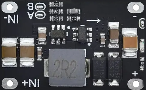
The DC-DC 3.7..5V 12/5/8/9V BS02 is a versatile voltage converter designed to step up or step down input voltage levels. It is commonly used to convert a 3.7V input (e.g., from a lithium-ion battery) to fixed output voltages of 5V, 8V, 9V, or 12V. This component is ideal for powering a wide range of electronic devices, including microcontrollers, sensors, and small appliances, where stable voltage is critical.
Explore Projects Built with DC-DC 3.7 BS02


Explore Projects Built with DC-DC 3.7 BS02
Common Applications
- Powering microcontrollers (e.g., Arduino, ESP32) from a 3.7V lithium-ion battery.
- Supplying stable voltage to sensors, modules, or small motors.
- Portable electronics and battery-powered devices.
- DIY projects requiring multiple voltage levels.
Technical Specifications
The following table outlines the key technical details of the DC-DC 3.7..5V 12/5/8/9V BS02:
| Parameter | Value |
|---|---|
| Input Voltage Range | 3.7V to 5V |
| Output Voltage Options | 5V, 8V, 9V, 12V (selectable) |
| Output Current | Up to 1A (varies with input/output voltage) |
| Efficiency | Up to 92% (depending on load and voltage) |
| Dimensions | Compact, typically 22mm x 17mm x 4mm |
| Operating Temperature | -40°C to +85°C |
Pin Configuration and Descriptions
The DC-DC converter module typically has the following pin layout:
| Pin Name | Description |
|---|---|
| VIN | Input voltage (3.7V to 5V) |
| GND | Ground (common for input and output) |
| VOUT | Output voltage (5V, 8V, 9V, or 12V, depending on selection) |
Usage Instructions
How to Use the Component in a Circuit
Connect the Input Voltage:
- Attach the positive terminal of your power source (e.g., a 3.7V lithium-ion battery) to the
VINpin. - Connect the negative terminal of the power source to the
GNDpin.
- Attach the positive terminal of your power source (e.g., a 3.7V lithium-ion battery) to the
Select the Desired Output Voltage:
- The module typically has a jumper or switch to select the output voltage (5V, 8V, 9V, or 12V). Refer to the specific module's labeling or datasheet for details.
Connect the Load:
- Attach the positive terminal of your load (e.g., a microcontroller or sensor) to the
VOUTpin. - Connect the negative terminal of your load to the
GNDpin.
- Attach the positive terminal of your load (e.g., a microcontroller or sensor) to the
Power On:
- Once all connections are secure, power on the input source. The module will regulate the input voltage to the selected output voltage.
Important Considerations and Best Practices
- Input Voltage Range: Ensure the input voltage is within the specified range (3.7V to 5V). Exceeding this range may damage the module.
- Output Current Limit: Do not exceed the maximum output current (1A). Overloading the module can cause overheating or failure.
- Heat Dissipation: For high current loads, ensure proper ventilation or add a heatsink to prevent overheating.
- Voltage Selection: Double-check the output voltage setting before connecting sensitive devices to avoid damage.
Example: Using with an Arduino UNO
To power an Arduino UNO from a 3.7V lithium-ion battery using this module:
- Set the output voltage to 5V using the jumper or switch.
- Connect the
VINpin of the module to the positive terminal of the battery. - Connect the
GNDpin of the module to the negative terminal of the battery. - Connect the
VOUTpin of the module to the5Vpin of the Arduino UNO. - Connect the
GNDpin of the module to theGNDpin of the Arduino UNO.
Here is an example Arduino sketch to blink an LED while powered by the module:
// Simple LED Blink Example
// This code blinks an LED connected to pin 13 of the Arduino UNO.
// Ensure the DC-DC converter is set to 5V output for powering the Arduino.

void setup() {
  pinMode(13, OUTPUT); // Set pin 13 as an output pin
}

void loop() {
  digitalWrite(13, HIGH); // Turn the LED on
  delay(1000);            // Wait for 1 second
  digitalWrite(13, LOW);  // Turn the LED off
  delay(1000);            // Wait for 1 second
}
Troubleshooting and FAQs
Common Issues and Solutions
No Output Voltage:
- Cause: Incorrect input voltage or loose connections.
- Solution: Verify that the input voltage is within the 3.7V to 5V range and check all connections.
Overheating:
- Cause: Excessive load or poor ventilation.
- Solution: Reduce the load current or add a heatsink to the module.
Incorrect Output Voltage:
- Cause: Output voltage not properly selected.
- Solution: Double-check the jumper or switch setting for the desired output voltage.
Device Not Powering On:
- Cause: Insufficient current supply or incorrect wiring.
- Solution: Ensure the input power source can supply enough current and verify all connections.
FAQs
Q: Can I use this module with a 3.3V input?
A: No, the input voltage must be within the 3.7V to 5V range for proper operation.
Q: How do I know the current output voltage?
A: Most modules have a label or indicator for the selected output voltage. Alternatively, use a multimeter to measure the output.
Q: Can I use this module to power a Raspberry Pi?
A: Yes, but ensure the output voltage is set to 5V and the current demand of the Raspberry Pi does not exceed 1A.
Q: Is the module protected against short circuits?
A: Some versions of this module include basic protection, but it is recommended to avoid short circuits to prevent damage.