How to Use T-Shape GPIO Extention Board: Examples, Pinouts, and Specs
Introduction
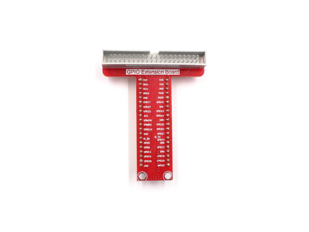
The HALJIA T-Shape GPIO Extension Board (Part ID: 1909002C) is a versatile and user-friendly component designed to expand the number of General Purpose Input/Output (GPIO) pins available for microcontrollers and single-board computers. Its T-shaped layout facilitates easier connections and prototyping, making it an essential tool for hobbyists, students, and professionals working on electronic projects.
Explore Projects Built with T-Shape GPIO Extention Board

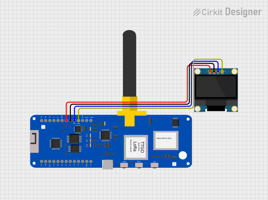
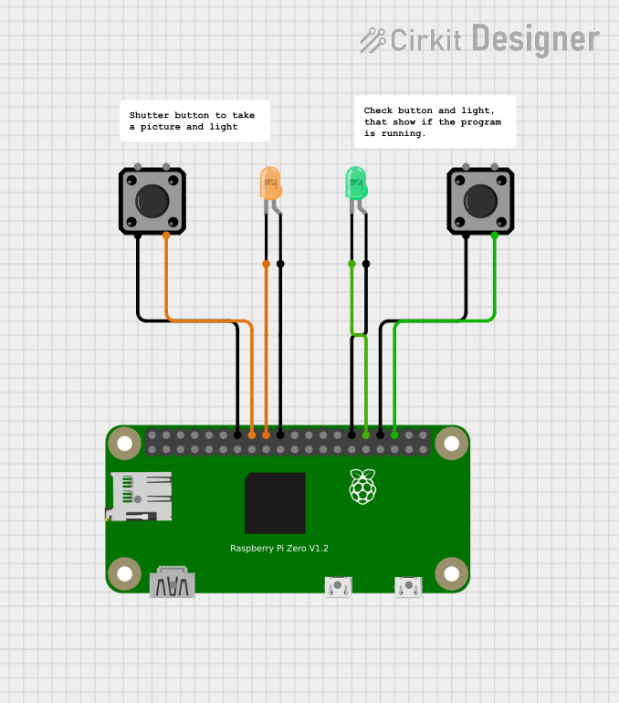

Explore Projects Built with T-Shape GPIO Extention Board
Common Applications and Use Cases
- Prototyping and Development: Ideal for breadboarding and testing new circuits.
- Educational Projects: Useful in teaching environments for demonstrating GPIO usage.
- IoT Projects: Expands GPIO capabilities for Internet of Things applications.
- Robotics: Provides additional GPIO pins for sensors, actuators, and other peripherals.
Technical Specifications
Key Technical Details
| Parameter | Specification |
|---|---|
| Manufacturer | HALJIA |
| Part ID | 1909002C |
| Voltage Rating | 3.3V/5V (compatible with most MCUs) |
| Current Rating | Up to 20mA per pin |
| Pin Count | 40 pins (20 on each side) |
| Dimensions | 60mm x 40mm x 10mm |
| Connector Type | Male and Female Headers |
Pin Configuration and Descriptions
| Pin Number | Description | Functionality |
|---|---|---|
| 1 | 3.3V | Power Supply (3.3V) |
| 2 | 5V | Power Supply (5V) |
| 3 | GPIO2 | General Purpose I/O |
| 4 | GPIO3 | General Purpose I/O |
| 5 | GND | Ground |
| 6 | GPIO4 | General Purpose I/O |
| 7 | GPIO5 | General Purpose I/O |
| 8 | GPIO6 | General Purpose I/O |
| 9 | GPIO7 | General Purpose I/O |
| 10 | GPIO8 | General Purpose I/O |
| 11 | GPIO9 | General Purpose I/O |
| 12 | GPIO10 | General Purpose I/O |
| 13 | GPIO11 | General Purpose I/O |
| 14 | GPIO12 | General Purpose I/O |
| 15 | GPIO13 | General Purpose I/O |
| 16 | GPIO14 | General Purpose I/O |
| 17 | GPIO15 | General Purpose I/O |
| 18 | GPIO16 | General Purpose I/O |
| 19 | GPIO17 | General Purpose I/O |
| 20 | GPIO18 | General Purpose I/O |
Usage Instructions
How to Use the Component in a Circuit
Power Supply:
- Connect the 3.3V or 5V pin to the corresponding power supply on your microcontroller.
- Connect the GND pin to the ground of your microcontroller.
Connecting GPIO Pins:
- Use jumper wires to connect the GPIO pins on the extension board to the desired pins on your microcontroller.
- Ensure that the GPIO pins are correctly mapped to the functions you intend to use.
Breadboarding:
- The T-shape layout is designed to fit easily on a breadboard, allowing for quick and efficient prototyping.
Important Considerations and Best Practices
- Voltage Compatibility: Ensure that the voltage levels of the GPIO pins are compatible with your microcontroller to avoid damage.
- Current Limitation: Do not exceed the current rating of 20mA per pin to prevent overheating and potential damage.
- Secure Connections: Make sure all connections are secure to avoid intermittent issues during operation.
Example: Connecting to an Arduino UNO
// Example code to blink an LED connected to GPIO2 on the T-Shape GPIO Extension Board

const int ledPin = 2; // GPIO2 on the extension board

void setup() {
  pinMode(ledPin, OUTPUT); // Set GPIO2 as an output
}

void loop() {
  digitalWrite(ledPin, HIGH); // Turn the LED on
  delay(1000);                // Wait for 1 second
  digitalWrite(ledPin, LOW);  // Turn the LED off
  delay(1000);                // Wait for 1 second
}
Troubleshooting and FAQs
Common Issues Users Might Face
No Power to the Board:
- Solution: Check the power supply connections to ensure they are correctly connected to the 3.3V or 5V and GND pins.
GPIO Pins Not Responding:
- Solution: Verify that the GPIO pins are correctly mapped and that the connections are secure. Check the microcontroller's code for any errors.
Intermittent Connections:
- Solution: Ensure that all jumper wires and connections are firmly in place. Consider using shorter wires to reduce potential issues.
FAQs
Q1: Can I use this extension board with a Raspberry Pi?
- A1: Yes, the HALJIA T-Shape GPIO Extension Board is compatible with Raspberry Pi and other single-board computers.
Q2: What is the maximum current I can draw from a single GPIO pin?
- A2: The maximum current rating for each GPIO pin is 20mA. Exceeding this limit may damage the board.
Q3: Can I use both 3.3V and 5V power supplies simultaneously?
- A3: No, you should use either the 3.3V or 5V power supply, not both at the same time, to avoid potential damage.
Q4: How do I know which GPIO pin corresponds to which function?
- A4: Refer to the pin configuration table provided in the technical specifications section of this documentation.
By following this documentation, users can effectively utilize the HALJIA T-Shape GPIO Extension Board to expand their GPIO capabilities and enhance their electronic projects.