How to Use Main Switch: Examples, Pinouts, and Specs
Introduction
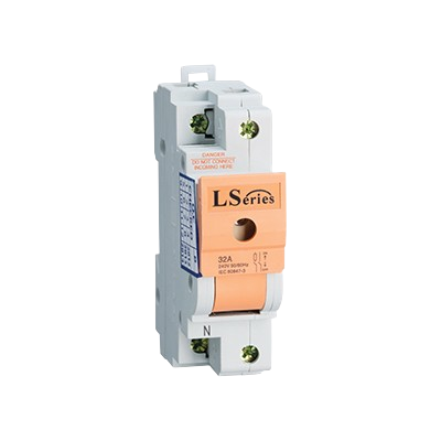
A Main Switch is a critical component in electrical systems, serving as the primary control mechanism for connecting or disconnecting the flow of electricity in a circuit. It is manually operated and is often used to control the main power supply to a building, machinery, or an electronic device. Common applications include residential and commercial electrical distribution panels, industrial control systems, and as a safety mechanism in various electronic projects.
Explore Projects Built with Main Switch


Explore Projects Built with Main Switch
Technical Specifications
General Characteristics
- Type: Mechanical Switch
- Function: Make or Break Electrical Connection
- Operation: Manual
Electrical Ratings
- Rated Voltage: Specified in volts (V), typically ranges from 110V to 600V depending on the model.
- Rated Current: Specified in amperes (A), commonly from 10A to several hundred amperes.
- Power Handling: Specified in watts (W) or kilowatts (kW), relevant to the switch's voltage and current ratings.
Mechanical Ratings
- Endurance: Number of operation cycles before failure, typically in the tens of thousands.
- Operating Temperature: Range in which the switch can operate reliably, e.g., -20°C to 60°C.
Pin Configuration and Descriptions
| Pin Number | Description | Notes |
|---|---|---|
| 1 | Line In (Live Input) | Connects to the live supply line |
| 2 | Load Out (Live Output) | Connects to the load or device |
| - | Earth/Ground | Safety connection (if applicable) |
| - | Neutral | Neutral line (if applicable) |
Note: The actual pin configuration may vary based on the design and manufacturer of the Main Switch. Always refer to the manufacturer's datasheet for the exact pinout.
Usage Instructions
Installation
- Power Off: Ensure that the power supply to the circuit where the Main Switch will be installed is turned off.
- Mounting: Secure the Main Switch to a suitable location, ensuring it is accessible for operation.
- Wiring: Connect the live supply line to the 'Line In' terminal and the load to the 'Load Out' terminal. If provided, connect the neutral and ground wires to their respective terminals.
- Inspection: Double-check all connections for correctness and tightness.
Operation
- To energize the circuit, manually toggle the switch to the 'ON' position.
- To de-energize the circuit, toggle the switch to the 'OFF' position.
Best Practices
- Always install a Main Switch with a current rating that exceeds the maximum expected load.
- Use appropriate cable sizes to prevent overheating and potential fire hazards.
- Regularly inspect the Main Switch for signs of wear or damage and replace if necessary.
Troubleshooting and FAQs
Common Issues
- Switch Does Not Operate: Check if the switch is jammed or if there is a mechanical failure.
- No Power to Load: Ensure the connections are secure and the switch is in the 'ON' position. Check for a blown fuse or tripped circuit breaker upstream of the Main Switch.
FAQs
Q: Can I replace a Main Switch myself? A: Replacing a Main Switch involves working with high-voltage electrical systems. It is recommended to hire a qualified electrician unless you have the proper training and experience.
Q: How do I know if my Main Switch is rated for my application? A: Check the switch's voltage and current ratings against the requirements of your electrical system. The ratings should meet or exceed your system's maximum operating parameters.
Q: What should I do if the Main Switch gets hot during operation? A: A hot switch may indicate an overloaded circuit or a loose connection. Turn off the power and inspect the switch and connections. If the issue persists, consult an electrician.
Note: This documentation is for informational purposes only. Always follow local codes and regulations when working with electrical components.
Since a Main Switch is not typically a component that would be connected to an Arduino UNO or similar microcontroller, code examples are not applicable for this documentation.