Cirkit Designer
Your all-in-one circuit design IDE
Home /
Component Documentation
How to Use LP-MSPM0G3507: Examples, Pinouts, and Specs
Introduction
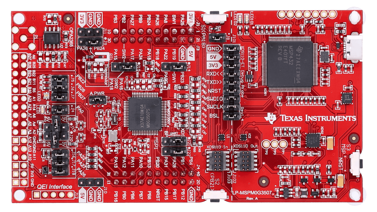
The LP-MSPM0G3507 is a LaunchPad development kit from Texas Instruments, featuring the MSPM0G3507 microcontroller. This microcontroller is designed for low-power and high-performance applications, making it ideal for a wide range of projects. The development kit includes various peripherals and interfaces, providing a comprehensive platform for prototyping and development.
Explore Projects Built with LP-MSPM0G3507
Battery-Powered Emergency Alert System with NUCLEO-F072RB, SIM800L, and GPS NEO 6M

This circuit is an emergency alert system that uses a NUCLEO-F072RB microcontroller to send SMS alerts and make calls via a SIM800L GSM module, while obtaining location data from a GPS NEO 6M module. The system is powered by a Li-ion battery and includes a TP4056 module for battery charging and protection, with a rocker switch to control power to the microcontroller.
Bluetooth Audio Receiver with Battery-Powered Amplifier and Loudspeakers

This circuit is a Bluetooth-enabled audio system powered by a rechargeable 18650 Li-ion battery. It includes a TP4056 module for battery charging and protection, a PAM8403 amplifier with volume control to drive two loudspeakers, and a Bluetooth audio receiver to wirelessly receive audio signals.
ESP32C3 and SIM800L Powered Smart Energy Monitor with OLED Display and Wi-Fi Connectivity

This circuit is a power monitoring system that uses an ESP32C3 microcontroller to collect power usage data from slave devices via WiFi and SMS. The collected data is displayed on a 0.96" OLED screen, and the system is powered by an AC-DC converter module. Additionally, the circuit includes a SIM800L GSM module for SMS communication and LEDs for status indication.
Cellular-Enabled IoT Device with Real-Time Clock and Power Management

This circuit features a LilyGo-SIM7000G module for cellular communication and GPS functionality, interfaced with an RTC DS3231 for real-time clock capabilities. It includes voltage sensing through two voltage sensor modules, and uses an 8-channel opto-coupler for isolating different parts of the circuit. Power management is handled by a buck converter connected to a DC power source and batteries, with a fuse for protection and a rocker switch for on/off control. Additionally, there's an LED for indication purposes.
Explore Projects Built with LP-MSPM0G3507
Battery-Powered Emergency Alert System with NUCLEO-F072RB, SIM800L, and GPS NEO 6M
This circuit is an emergency alert system that uses a NUCLEO-F072RB microcontroller to send SMS alerts and make calls via a SIM800L GSM module, while obtaining location data from a GPS NEO 6M module. The system is powered by a Li-ion battery and includes a TP4056 module for battery charging and protection, with a rocker switch to control power to the microcontroller.
Bluetooth Audio Receiver with Battery-Powered Amplifier and Loudspeakers
This circuit is a Bluetooth-enabled audio system powered by a rechargeable 18650 Li-ion battery. It includes a TP4056 module for battery charging and protection, a PAM8403 amplifier with volume control to drive two loudspeakers, and a Bluetooth audio receiver to wirelessly receive audio signals.
ESP32C3 and SIM800L Powered Smart Energy Monitor with OLED Display and Wi-Fi Connectivity
This circuit is a power monitoring system that uses an ESP32C3 microcontroller to collect power usage data from slave devices via WiFi and SMS. The collected data is displayed on a 0.96" OLED screen, and the system is powered by an AC-DC converter module. Additionally, the circuit includes a SIM800L GSM module for SMS communication and LEDs for status indication.
Cellular-Enabled IoT Device with Real-Time Clock and Power Management
This circuit features a LilyGo-SIM7000G module for cellular communication and GPS functionality, interfaced with an RTC DS3231 for real-time clock capabilities. It includes voltage sensing through two voltage sensor modules, and uses an 8-channel opto-coupler for isolating different parts of the circuit. Power management is handled by a buck converter connected to a DC power source and batteries, with a fuse for protection and a rocker switch for on/off control. Additionally, there's an LED for indication purposes.
Common Applications and Use Cases
- Embedded Systems: Ideal for developing embedded applications requiring low power consumption and high performance.
- IoT Devices: Suitable for Internet of Things (IoT) projects due to its low power and connectivity features.
- Prototyping: Perfect for rapid prototyping and development of new electronic devices.
- Educational Purposes: Great for learning and teaching microcontroller programming and embedded system design.
Technical Specifications
Key Technical Details
| Specification | Value |
|---|---|
| Microcontroller | MSPM0G3507 |
| Operating Voltage | 1.8V to 3.6V |
| Flash Memory | 128 KB |
| RAM | 32 KB |
| GPIO Pins | 40 |
| Communication | UART, I2C, SPI, CAN, USB |
| ADC | 12-bit, 16 channels |
| Timers | 4 (16-bit) |
| PWM Channels | 8 |
| Operating Temperature | -40°C to 85°C |
Pin Configuration and Descriptions
| Pin Number | Pin Name | Description |
|---|---|---|
| 1 | VCC | Power Supply (1.8V to 3.6V) |
| 2 | GND | Ground |
| 3 | P1.0 | GPIO / ADC Channel 0 |
| 4 | P1.1 | GPIO / ADC Channel 1 |
| 5 | P1.2 | GPIO / ADC Channel 2 |
| 6 | P1.3 | GPIO / ADC Channel 3 |
| 7 | P1.4 | GPIO / ADC Channel 4 |
| 8 | P1.5 | GPIO / ADC Channel 5 |
| 9 | P1.6 | GPIO / ADC Channel 6 |
| 10 | P1.7 | GPIO / ADC Channel 7 |
| 11 | P2.0 | GPIO / PWM Channel 0 |
| 12 | P2.1 | GPIO / PWM Channel 1 |
| 13 | P2.2 | GPIO / PWM Channel 2 |
| 14 | P2.3 | GPIO / PWM Channel 3 |
| 15 | P2.4 | GPIO / PWM Channel 4 |
| 16 | P2.5 | GPIO / PWM Channel 5 |
| 17 | P2.6 | GPIO / PWM Channel 6 |
| 18 | P2.7 | GPIO / PWM Channel 7 |
| 19 | UART_TX | UART Transmit |
| 20 | UART_RX | UART Receive |
| 21 | I2C_SCL | I2C Clock |
| 22 | I2C_SDA | I2C Data |
| 23 | SPI_MOSI | SPI Master Out Slave In |
| 24 | SPI_MISO | SPI Master In Slave Out |
| 25 | SPI_SCK | SPI Clock |
| 26 | SPI_CS | SPI Chip Select |
| 27 | CAN_TX | CAN Transmit |
| 28 | CAN_RX | CAN Receive |
| 29 | USB_DM | USB Data Minus |
| 30 | USB_DP | USB Data Plus |
| 31-40 | NC | Not Connected |
Usage Instructions
How to Use the Component in a Circuit
- Power Supply: Connect the VCC pin to a power supply (1.8V to 3.6V) and the GND pin to ground.
- GPIO Configuration: Use the GPIO pins for digital input/output operations. Configure the pins as needed in your code.
- Communication Interfaces: Utilize UART, I2C, SPI, and CAN interfaces for communication with other devices.
- Analog Inputs: Use the ADC channels for analog input readings.
- PWM Outputs: Use the PWM channels for generating pulse-width modulated signals.
Important Considerations and Best Practices
- Power Supply: Ensure the power supply voltage is within the specified range (1.8V to 3.6V) to avoid damaging the microcontroller.
- Pin Configuration: Properly configure the pins in your code to match your circuit design.
- Decoupling Capacitors: Use decoupling capacitors close to the power pins to reduce noise and improve stability.
- Code Optimization: Optimize your code for low power consumption, especially in battery-powered applications.
Example Code for Arduino UNO
// Example code to interface LP-MSPM0G3507 with Arduino UNO
// This code reads an analog value from the MSPM0G3507 and sends it to the
// Arduino UNO via UART

#include <SoftwareSerial.h>

SoftwareSerial mySerial(10, 11); // RX, TX

void setup() {
  Serial.begin(9600); // Initialize serial communication at 9600 baud
  mySerial.begin(9600); // Initialize software serial communication
}

void loop() {
  if (mySerial.available()) {
    int analogValue = mySerial.parseInt(); // Read the analog value
    Serial.print("Analog Value: ");
    Serial.println(analogValue); // Print the analog value to the serial monitor
  }
  delay(1000); // Wait for 1 second
}
Troubleshooting and FAQs
Common Issues Users Might Face
Microcontroller Not Powering On:
- Solution: Check the power supply voltage and connections. Ensure the VCC and GND pins are properly connected.
Incorrect Analog Readings:
- Solution: Verify the ADC pin connections and ensure the input voltage is within the ADC range. Check for noise and interference in the analog signal.
Communication Interface Not Working:
- Solution: Double-check the pin configurations and connections for UART, I2C, SPI, or CAN interfaces. Ensure the correct baud rate and settings are used in the code.
Microcontroller Overheating:
- Solution: Ensure the power supply voltage is within the specified range. Check for short circuits or excessive current draw in the circuit.
Solutions and Tips for Troubleshooting
- Use a Multimeter: Measure voltages and check connections to identify issues.
- Check Code: Review and debug your code to ensure proper pin configurations and settings.
- Consult Datasheet: Refer to the MSPM0G3507 datasheet for detailed information on pin functions and electrical characteristics.
- Use Decoupling Capacitors: Place decoupling capacitors close to the power pins to reduce noise and improve stability.
By following this documentation, users can effectively utilize the LP-MSPM0G3507 LaunchPad development kit for their projects, ensuring optimal performance and reliability.