
How to Use Espruino Pico: Examples, Pinouts, and Specs
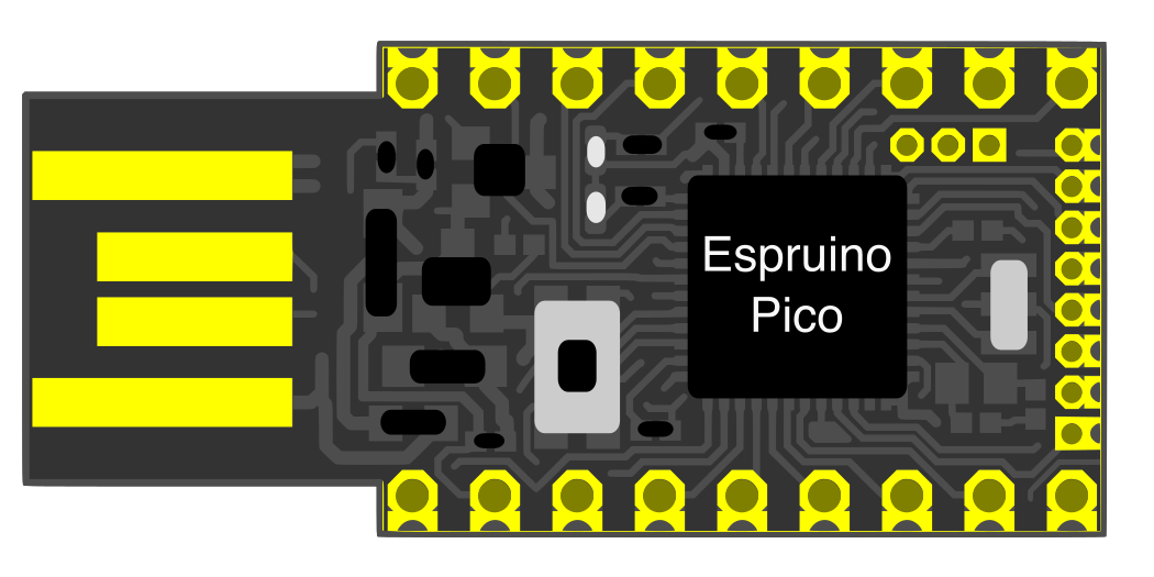
 Design with Espruino Pico in Cirkit Designer
Introduction
The Espruino Pico is a compact, low-power microcontroller board designed by Espruino. It is unique in its ability to run JavaScript directly on the hardware, making it an excellent choice for Internet of Things (IoT) applications and rapid prototyping. With its small form factor and USB plug, the Espruino Pico is easy to integrate into projects, even in space-constrained environments.
Explore Projects Built with Espruino Pico
 Open Project in Cirkit Designer
 Open Project in Cirkit Designer
 Open Project in Cirkit Designer
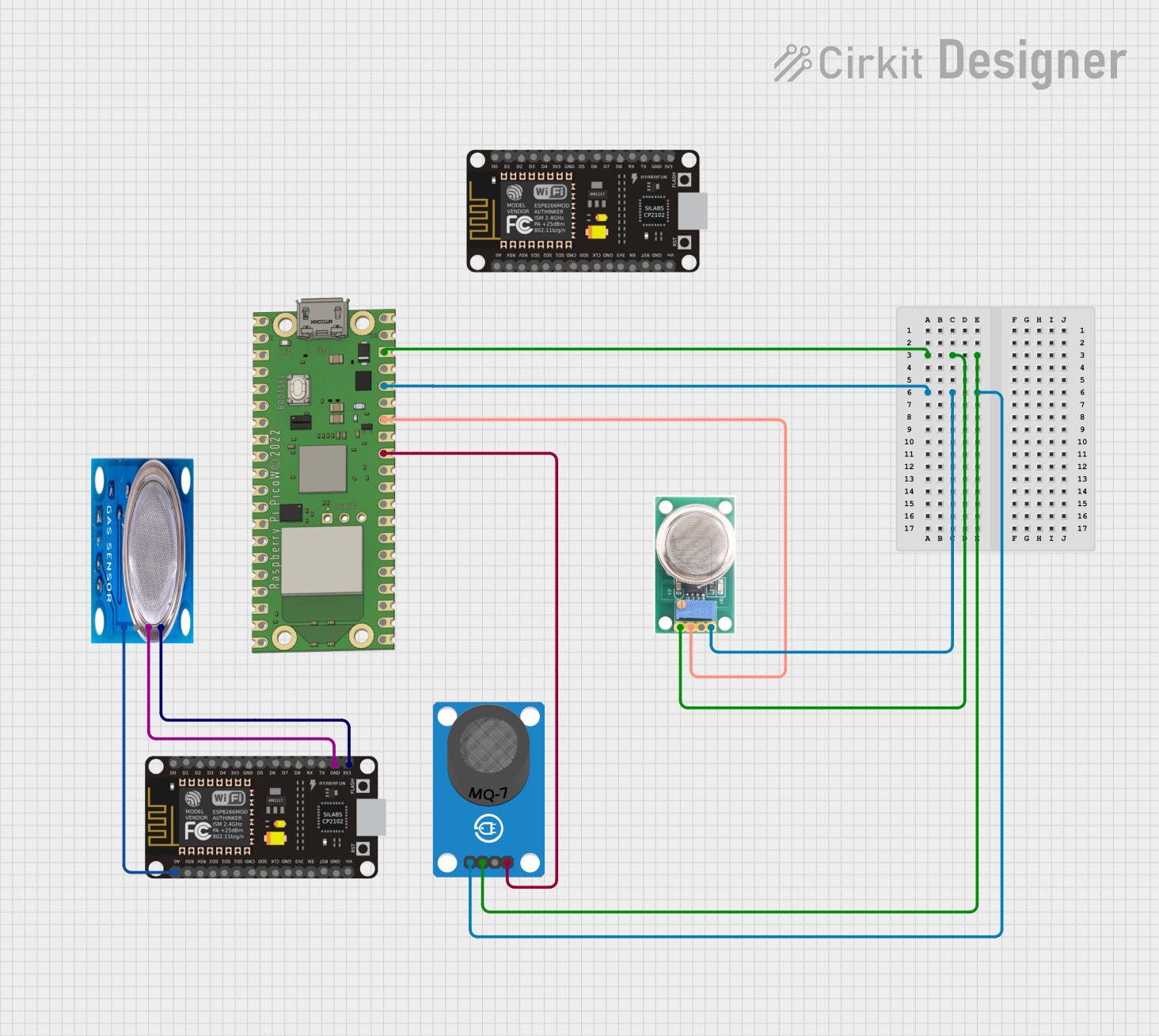 Open Project in Cirkit Designer
Explore Projects Built with Espruino Pico
Open Project in Cirkit DesignerOpen Project in Cirkit DesignerOpen Project in Cirkit DesignerOpen Project in Cirkit DesignerCommon Applications and Use Cases
- IoT devices and smart home automation
- Rapid prototyping for embedded systems
- Educational projects for learning JavaScript and hardware programming
- Wearable technology
- Low-power data logging and sensor interfacing
Technical Specifications
The Espruino Pico is packed with features that make it versatile and easy to use. Below are its key technical details:
Key Technical Details
- Microcontroller: STM32F401CDU6 (ARM Cortex-M4, 32-bit)
- Clock Speed: 84 MHz
- Flash Memory: 384 KB (256 KB available for user code)
- RAM: 96 KB
- Power Supply: 3.3V to 16V (via VBAT pin) or 5V (via USB)
- USB Interface: Full-speed USB 2.0
- GPIO Pins: 22 (including analog, PWM, and digital I/O)
- Analog Inputs: 9 (12-bit ADC)
- PWM Outputs: 21
- Communication Protocols: UART, I2C, SPI
- Dimensions: 33 mm x 15 mm x 5 mm
- Power Consumption: ~0.1 mA in deep sleep mode
Pin Configuration and Descriptions
The Espruino Pico has 22 GPIO pins, each with multiple functions. Below is the pinout description:
| Pin | Function | Description |
|---|---|---|
| GND | Ground | Common ground for the circuit. |
| 3.3V | Power Output | Provides 3.3V output for powering external components. |
| VBAT | Power Input | Accepts 3.3V to 16V for powering the board. |
| D0-D21 | GPIO Pins | General-purpose I/O pins with support for digital, analog, and PWM functions. |
| A0-A8 | Analog Inputs | 12-bit ADC pins for reading analog signals. |
| TX/RX | UART Communication | Serial communication pins for UART. |
| SCL/SDA | I2C Communication | Clock and data lines for I2C communication. |
| SCK/MISO/MOSI | SPI Communication | Serial clock, master-in-slave-out, and master-out-slave-in for SPI. |
| USB+ | USB Data Positive | USB data line for communication. |
| USB- | USB Data Negative | USB data line for communication. |
Usage Instructions
The Espruino Pico is designed to be easy to use, even for beginners. Below are the steps to get started and some best practices for using the board.
How to Use the Espruino Pico in a Circuit
Powering the Board:
- Connect the Espruino Pico to a USB port for power and programming.
- Alternatively, supply 3.3V to 16V to the VBAT pin for standalone operation.
Programming the Board:
- Install the Espruino Web IDE (available as a Chrome app or standalone software).
- Connect the board to your computer via USB.
- Open the Espruino Web IDE, select the correct COM port, and start writing JavaScript code.
Connecting Components:
- Use the GPIO pins to connect sensors, actuators, or other peripherals.
- Ensure proper voltage levels and use resistors or level shifters if necessary.
Running Code:
- Write JavaScript code in the Espruino Web IDE.
- Upload the code to the board and see it execute in real-time.
Important Considerations and Best Practices
- Power Supply: Ensure the power supply voltage is within the specified range to avoid damaging the board.
- Pin Usage: Avoid exceeding the maximum current rating of the GPIO pins (20 mA per pin).
- Deep Sleep Mode: Use deep sleep mode to minimize power consumption in battery-powered applications.
- Static Protection: Handle the board with care to avoid damage from electrostatic discharge (ESD).
Example Code for Arduino UNO Users
The Espruino Pico can be programmed directly in JavaScript, but here’s an example of how to blink an LED connected to pin D13:
// Blink an LED connected to pin D13
var led = D13; // Define the pin connected to the LED

// Function to toggle the LED state
function toggleLED() {
  digitalWrite(led, !digitalRead(led)); // Toggle the LED state
}

// Set an interval to toggle the LED every 500ms
setInterval(toggleLED, 500);
Troubleshooting and FAQs
Common Issues and Solutions
The board is not detected by the Espruino Web IDE:
- Ensure the USB cable is functional and supports data transfer.
- Check that the correct COM port is selected in the IDE.
- Try pressing the reset button on the board.
Code does not execute as expected:
- Verify that the code is free of syntax errors.
- Check the pin connections and ensure they match the code.
The board overheats or does not power on:
- Ensure the power supply voltage is within the specified range (3.3V to 16V).
- Check for short circuits in the connected components.
Unable to connect to peripherals (e.g., sensors):
- Verify the wiring and ensure the correct communication protocol (I2C, SPI, UART) is used.
- Check the peripheral's datasheet for compatibility and configuration details.
FAQs
Q: Can I use the Espruino Pico with batteries?
A: Yes, you can power the board using batteries by connecting them to the VBAT pin. Ensure the voltage is between 3.3V and 16V.
Q: Is the Espruino Pico compatible with Arduino libraries?
A: No, the Espruino Pico uses JavaScript instead of C/C++. However, many libraries and examples are available in the Espruino ecosystem.
Q: How do I reset the board to factory settings?
A: Hold down the button on the board while plugging it into USB. Release the button when the red LED starts flashing.
Q: Can I use the Espruino Pico for real-time applications?
A: Yes, the Espruino Pico is capable of handling real-time tasks, but keep in mind that JavaScript is an interpreted language, so performance may vary.
This concludes the documentation for the Espruino Pico. For more information, visit the official Espruino website.