Cirkit Designer Logo
Cirkit Designer
Your all-in-one circuit design IDE
Home / 
Component Documentation

How to Use LED: Two Pin (orange): Examples, Pinouts, and Specs

Image of LED: Two Pin (orange)
Cirkit Designer LogoDesign with LED: Two Pin (orange) in Cirkit Designer

Introduction

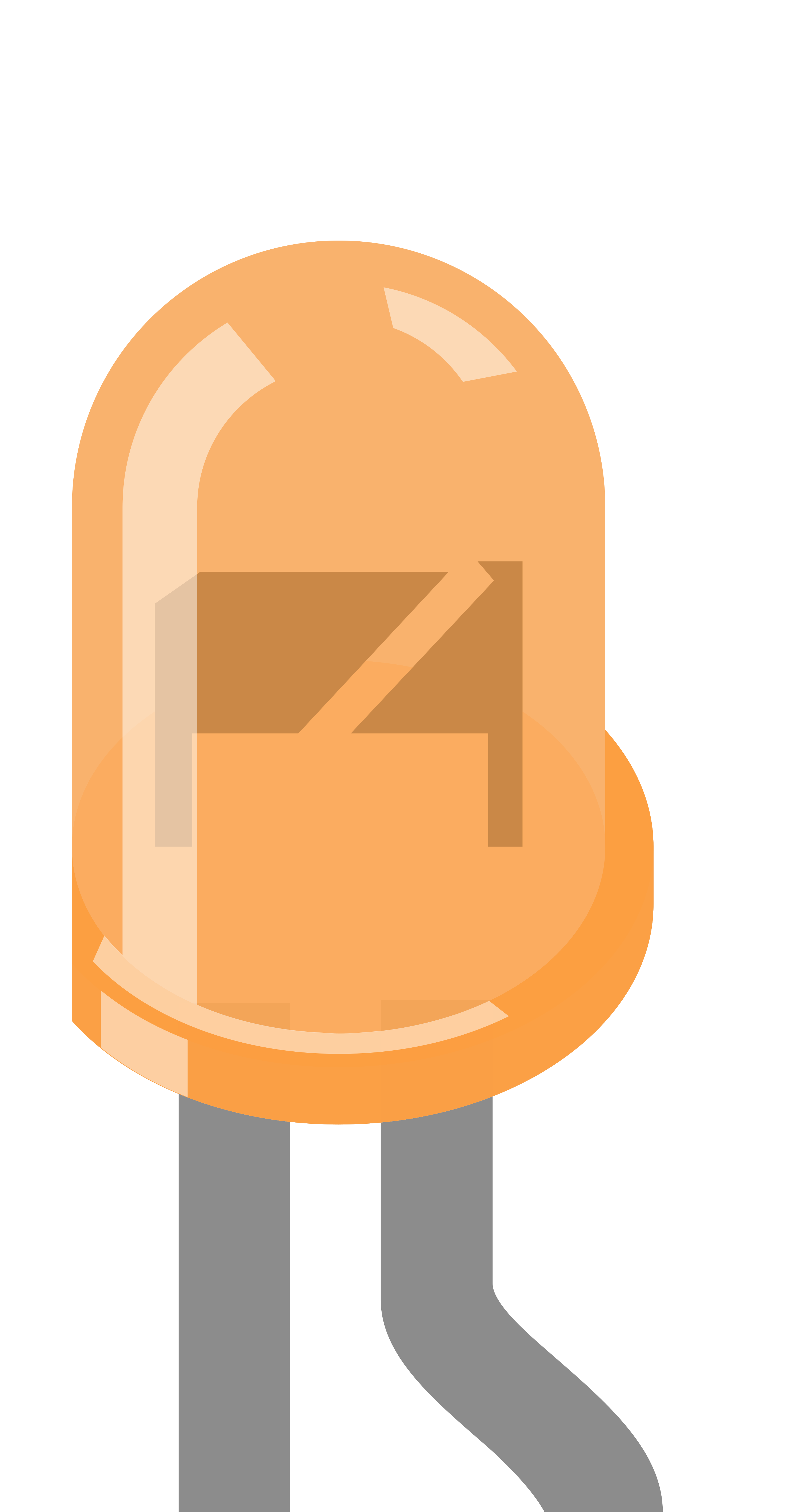
An orange LED (Light-Emitting Diode) with two pins is a semiconductor device that emits orange light when an electric current passes through it. LEDs are widely used in various applications due to their low power consumption, long life, and compact size. Common applications for orange LEDs include indicator lights, display panels, and decorative lighting.

Explore Projects Built with LED: Two Pin (orange)

Use Cirkit Designer to design, explore, and prototype these projects online. Some projects support real-time simulation. Click "Open Project" to start designing instantly!
LED Array with Inductive Power Transfer
Image of Wind Mill: A project utilizing LED: Two Pin (orange) in a practical application
The circuit consists of multiple red two-pin LEDs connected in parallel, with all cathodes tied together and all anodes tied together. A copper coil is also connected in parallel with the LEDs. There is no control circuitry or power regulation components indicated, and no embedded code provided, suggesting this is a simple illumination circuit possibly intended for inductive power transfer given the presence of the copper coil.
Cirkit Designer LogoOpen Project in Cirkit Designer
Simple LED Circuit with Current-Limiting Resistors
Image of 모스시: A project utilizing LED: Two Pin (orange) in a practical application
The circuit consists of two independent sections, each containing a red LED in series with a 220-ohm resistor. The purpose of this circuit is likely for simple indication, with the resistors serving to limit the current through the LEDs to prevent damage.
Cirkit Designer LogoOpen Project in Cirkit Designer
Pushbutton-Controlled Dual-Color LED Circuit with TA6568
Image of polarity detector: A project utilizing LED: Two Pin (orange) in a practical application
This is a pushbutton-controlled LED circuit with a TA6568 chip that likely drives two LEDs (red and green). Each LED is connected to a pushbutton through the TA6568, allowing the user to toggle the state of the LEDs. The circuit is powered by a 3V battery and includes a JST connector for external interfacing.
Cirkit Designer LogoOpen Project in Cirkit Designer
Arduino UNO Controlled Blinking LED Circuit
Image of led: A project utilizing LED: Two Pin (orange) in a practical application
This circuit consists of an Arduino UNO microcontroller connected to a red two-pin LED. The Arduino's digital pin D13 is connected to the LED's anode, and the LED's cathode is connected to the Arduino's ground (GND). The embedded code on the Arduino is programmed to blink the LED on and off at one-second intervals.
Cirkit Designer LogoOpen Project in Cirkit Designer

Explore Projects Built with LED: Two Pin (orange)

Use Cirkit Designer to design, explore, and prototype these projects online. Some projects support real-time simulation. Click "Open Project" to start designing instantly!
Image of Wind Mill: A project utilizing LED: Two Pin (orange) in a practical application
LED Array with Inductive Power Transfer
The circuit consists of multiple red two-pin LEDs connected in parallel, with all cathodes tied together and all anodes tied together. A copper coil is also connected in parallel with the LEDs. There is no control circuitry or power regulation components indicated, and no embedded code provided, suggesting this is a simple illumination circuit possibly intended for inductive power transfer given the presence of the copper coil.
Cirkit Designer LogoOpen Project in Cirkit Designer
Image of 모스시: A project utilizing LED: Two Pin (orange) in a practical application
Simple LED Circuit with Current-Limiting Resistors
The circuit consists of two independent sections, each containing a red LED in series with a 220-ohm resistor. The purpose of this circuit is likely for simple indication, with the resistors serving to limit the current through the LEDs to prevent damage.
Cirkit Designer LogoOpen Project in Cirkit Designer
Image of polarity detector: A project utilizing LED: Two Pin (orange) in a practical application
Pushbutton-Controlled Dual-Color LED Circuit with TA6568
This is a pushbutton-controlled LED circuit with a TA6568 chip that likely drives two LEDs (red and green). Each LED is connected to a pushbutton through the TA6568, allowing the user to toggle the state of the LEDs. The circuit is powered by a 3V battery and includes a JST connector for external interfacing.
Cirkit Designer LogoOpen Project in Cirkit Designer
Image of led: A project utilizing LED: Two Pin (orange) in a practical application
Arduino UNO Controlled Blinking LED Circuit
This circuit consists of an Arduino UNO microcontroller connected to a red two-pin LED. The Arduino's digital pin D13 is connected to the LED's anode, and the LED's cathode is connected to the Arduino's ground (GND). The embedded code on the Arduino is programmed to blink the LED on and off at one-second intervals.
Cirkit Designer LogoOpen Project in Cirkit Designer

Technical Specifications

General Characteristics

  • Color: Orange
  • Lens Type: Water clear or diffused
  • Luminous Intensity: Typically measured in mcd (millicandela)
  • Viewing Angle: Specified in degrees (°)

Electrical Characteristics

  • Forward Voltage (Vf): Typically 1.8V to 2.2V
  • Forward Current (If): Recommended 20mA (max. current without risking damage)
  • Reverse Voltage (Vr): Typically 5V (maximum voltage before reverse breakdown)
  • Power Dissipation: Varies with size and type, usually around 100mW

Pin Configuration

Pin Number Description
1 Anode (+)
2 Cathode (-)

Usage Instructions

Connecting to a Circuit

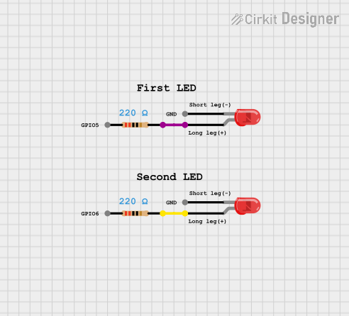
  1. Identify the Pins: The longer pin is usually the anode (+), and the shorter pin is the cathode (-). Alternatively, the flat side of the LED lens indicates the cathode side.
  2. Current Limiting Resistor: Always use a current limiting resistor in series with the LED to prevent it from drawing too much current. The value of the resistor can be calculated using Ohm's Law: R = (Vsource - Vf) / If, where Vsource is the voltage of your power supply.
  3. Polarity: Ensure that the LED is connected with the correct polarity, with the anode connected to the positive voltage and the cathode to the negative or ground.

Best Practices

  • Avoid exceeding the maximum ratings for forward current and reverse voltage.
  • Use a resistor with a power rating that can handle the power dissipation.
  • When using multiple LEDs, connect each with its own current limiting resistor to ensure uniform brightness.

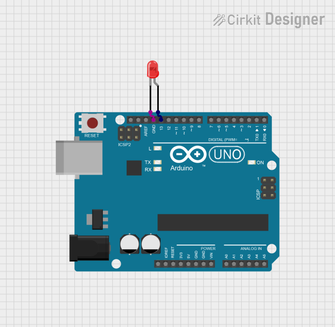
Example Arduino UNO Connection

// Define the pin connected to the LED
const int ledPin = 13; // Built-in LED pin on Arduino UNO

void setup() {
  pinMode(ledPin, OUTPUT); // Set the LED pin as an output
}

void loop() {
  digitalWrite(ledPin, HIGH); // Turn the LED on
  delay(1000);                // Wait for a second
  digitalWrite(ledPin, LOW);  // Turn the LED off
  delay(1000);                // Wait for a second
}

Note: When connecting an external orange LED to an Arduino UNO, ensure you use a current limiting resistor (e.g., 220Ω for a 5V supply) between the digital pin and the anode of the LED.

Troubleshooting and FAQs

Common Issues

  • LED not lighting up: Check the polarity of the LED and ensure the current limiting resistor is correctly calculated and connected.
  • Dim LED: The current limiting resistor may be too high, or the power supply voltage may be too low.
  • LED burned out: The current limiting resistor may be too low, or the LED was connected without a resistor.

FAQs

Q: Can I connect an LED directly to a battery?
A: No, you should always use a current limiting resistor to prevent damage to the LED.

Q: How do I know if my LED is damaged?
A: An LED that does not light up when correctly connected may be damaged. Use a multimeter to check for continuity.

Q: Can I use a variable resistor to adjust the brightness of the LED?
A: Yes, a potentiometer can be used in series with the LED to vary the current and adjust brightness.

For further assistance, please refer to the manufacturer's datasheet or contact technical support.