How to Use Charging Module: Examples, Pinouts, and Specs
Introduction
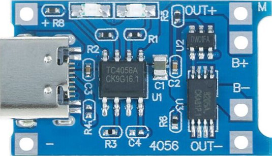
The Charging Module (Type-C) by Generic is a compact and efficient device designed to manage the charging of batteries. It ensures safe and reliable charging by regulating voltage and current, protecting batteries from overcharging, and extending their lifespan. This module is particularly useful for lithium-ion and lithium-polymer batteries, which require precise charging control.
Explore Projects Built with Charging Module


Explore Projects Built with Charging Module
Common Applications and Use Cases
- Charging lithium-ion and lithium-polymer batteries in portable devices
- Power banks and battery-powered projects
- DIY electronics and robotics
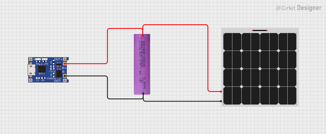
- Solar-powered battery charging systems
- Educational and prototyping purposes
Technical Specifications
The following table outlines the key technical details of the Charging Module (Type-C):
| Parameter | Value |
|---|---|
| Input Voltage | 5V DC (via USB Type-C connector) |
| Charging Current | 1A (default), adjustable up to 2A |
| Battery Type Supported | Lithium-ion, Lithium-polymer |
| Charging Voltage | 4.2V (±1%) |
| Protection Features | Overcharge, Overcurrent, Short Circuit |
| Dimensions | 25mm x 19mm x 5mm |
Pin Configuration and Descriptions
The Charging Module has the following pins and connectors:
| Pin/Connector | Description |
|---|---|
| Type-C Input | USB Type-C connector for 5V DC input power. |
| BAT+ | Positive terminal for connecting the battery. |
| BAT- | Negative terminal for connecting the battery. |
| OUT+ | Positive terminal for output voltage (connected to the load). |
| OUT- | Negative terminal for output voltage (connected to the load). |
| PROG | Pin to adjust the charging current by connecting an external resistor. |
| STAT1/STAT2 | Status indicator pins for charging (can be connected to LEDs for visual status). |
Usage Instructions
How to Use the Charging Module in a Circuit
- Power Input: Connect a 5V DC power source to the USB Type-C input connector. This can be a USB adapter, power bank, or any 5V DC source.
- Battery Connection:
- Connect the positive terminal of the battery to the
BAT+pin. - Connect the negative terminal of the battery to the
BAT-pin.
- Connect the positive terminal of the battery to the
- Load Connection (Optional):
- If you want to power a load while charging the battery, connect the load's positive terminal to
OUT+and the negative terminal toOUT-.
- If you want to power a load while charging the battery, connect the load's positive terminal to
- Adjusting Charging Current:
- The default charging current is 1A. To adjust it, connect a resistor to the
PROGpin. Refer to the module's datasheet for the resistor value corresponding to the desired current.
- The default charging current is 1A. To adjust it, connect a resistor to the
- Status Indicators:
- Connect LEDs to the
STAT1andSTAT2pins to monitor the charging status. Typically, one LED indicates charging, and the other indicates a fully charged battery.
- Connect LEDs to the
Important Considerations and Best Practices
- Ensure the input voltage is stable and within the specified range (5V DC).
- Use appropriate wiring and connectors to handle the charging current without overheating.
- Avoid short-circuiting the
BAT+andBAT-terminals. - Do not exceed the recommended charging current for your battery to prevent damage.
- Place the module in a well-ventilated area to prevent overheating during operation.
Example: Using the Charging Module with an Arduino UNO
The Charging Module can be used to power an Arduino UNO while charging a battery. Below is an example circuit and code:
Circuit Connections
- Connect the
OUT+andOUT-pins of the Charging Module to the Arduino UNO'sVINandGNDpins, respectively. - Connect a 3.7V lithium-ion battery to the
BAT+andBAT-pins of the module. - Power the module using a USB Type-C cable connected to a 5V DC source.
Example Code
// Example code to monitor battery voltage using Arduino UNO
// Connect the battery's positive terminal to an analog pin (e.g., A0)

const int batteryPin = A0; // Analog pin connected to battery positive terminal
float batteryVoltage = 0.0;

void setup() {
  Serial.begin(9600); // Initialize serial communication
  pinMode(batteryPin, INPUT); // Set the battery pin as input
}

void loop() {
  int sensorValue = analogRead(batteryPin); // Read the analog value
  // Convert the analog value to voltage (assuming a 5V reference and 10-bit ADC)
  batteryVoltage = sensorValue * (5.0 / 1023.0) * 2;
  // Multiply by 2 if a voltage divider is used to measure higher voltages

  Serial.print("Battery Voltage: ");
  Serial.print(batteryVoltage);
  Serial.println(" V");

  delay(1000); // Wait for 1 second before the next reading
}
Troubleshooting and FAQs
Common Issues and Solutions
Module Overheating:
- Cause: Excessive charging current or poor ventilation.
- Solution: Reduce the charging current by adjusting the resistor on the
PROGpin. Ensure proper airflow around the module.
Battery Not Charging:
- Cause: Incorrect wiring or a faulty battery.
- Solution: Double-check the connections to
BAT+andBAT-. Test the battery with a multimeter to ensure it is functional.
No Output Voltage:
- Cause: The battery is not connected, or the module is not powered.
- Solution: Ensure the battery is properly connected and the module is receiving 5V input power.
LED Indicators Not Working:
- Cause: LEDs are not connected correctly or are damaged.
- Solution: Verify the connections to
STAT1andSTAT2. Replace the LEDs if necessary.
FAQs
Can I use this module to charge batteries other than lithium-ion or lithium-polymer?
- No, this module is specifically designed for lithium-ion and lithium-polymer batteries. Using it with other battery types may result in damage.
What is the maximum battery capacity this module can charge?
- The module can charge batteries of any capacity, but the charging time will increase with larger capacities.
Can I use this module without a battery, as a power supply?
- Yes, you can use the
OUT+andOUT-pins to power a load directly, but ensure the load does not exceed the module's current rating.
- Yes, you can use the
How do I adjust the charging current?
- Connect a resistor to the
PROGpin. Refer to the module's datasheet for the resistor value corresponding to the desired current.
- Connect a resistor to the
By following this documentation, you can safely and effectively use the Charging Module (Type-C) in your projects.