How to Use DHT21: Examples, Pinouts, and Specs
Introduction
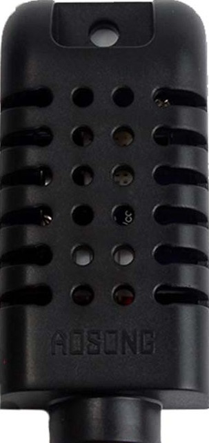
The DHT21 is a digital temperature and humidity sensor that provides accurate readings of environmental conditions. It is designed to measure relative humidity and temperature with high precision and stability. The sensor communicates via a single-wire interface, making it easy to integrate into microcontroller-based systems. Its compact design and reliable performance make it a popular choice for a variety of applications.
Explore Projects Built with DHT21
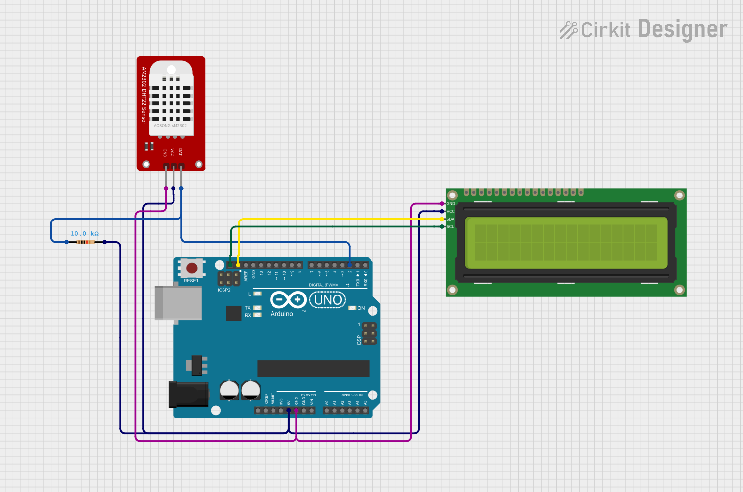

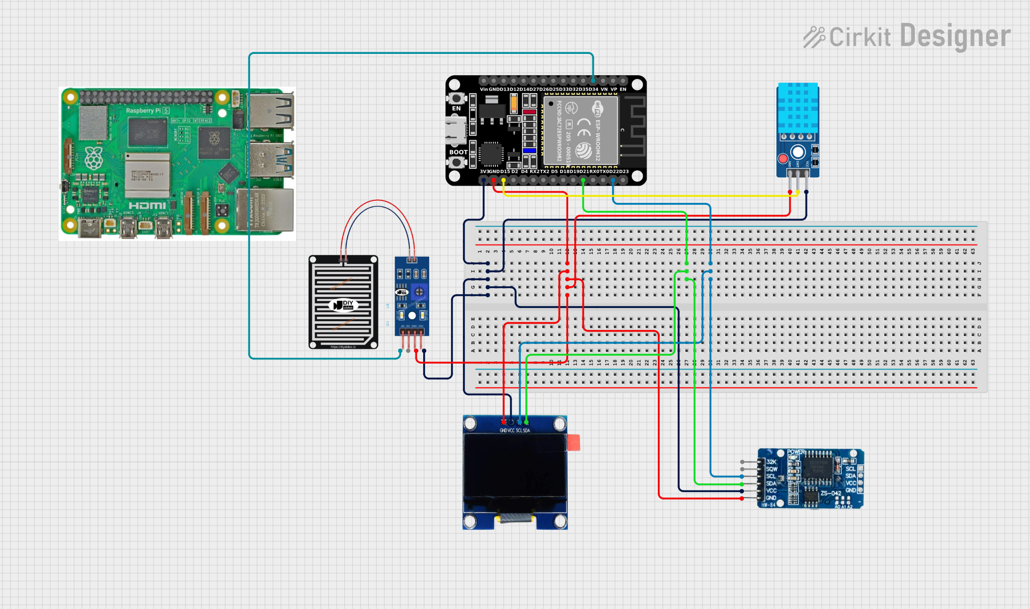
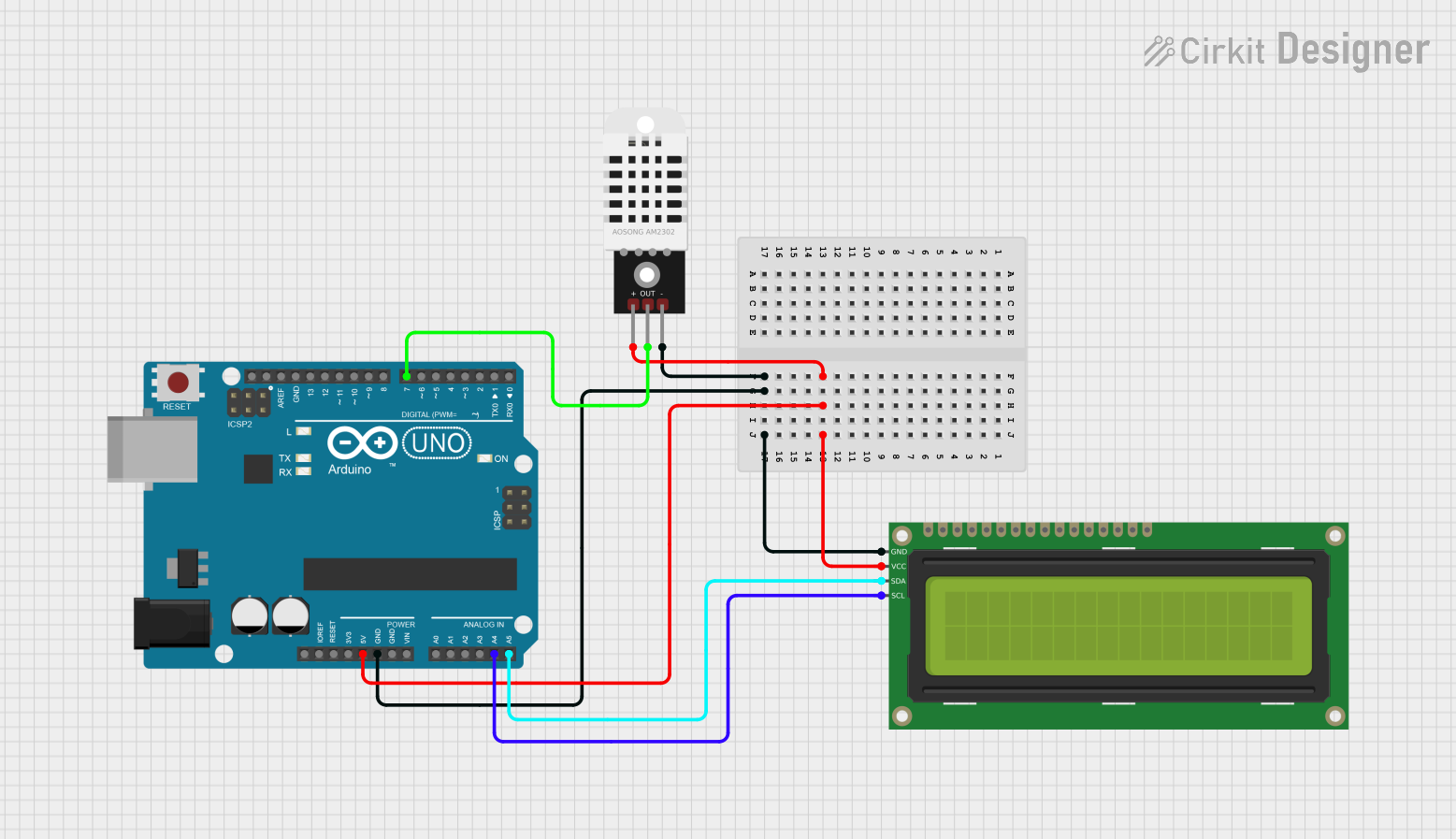
Explore Projects Built with DHT21
Common Applications
- Weather monitoring stations
- HVAC (Heating, Ventilation, and Air Conditioning) systems
- Home automation and IoT projects
- Greenhouse monitoring
- Industrial environmental monitoring
Technical Specifications
The DHT21 sensor is designed to deliver reliable and accurate measurements. Below are its key technical details:
| Parameter | Value |
|---|---|
| Supply Voltage | 3.3V to 5.5V |
| Operating Current | 0.3 mA (measuring), 60 µA (standby) |
| Humidity Range | 0% to 100% RH |
| Humidity Accuracy | ±2% RH |
| Temperature Range | -40°C to 80°C |
| Temperature Accuracy | ±0.5°C |
| Communication Interface | Single-wire (digital) |
| Sampling Period | 2 seconds |
| Dimensions | 27mm x 58mm x 13mm |
Pin Configuration
The DHT21 has four pins, as described in the table below:
| Pin Number | Name | Description |
|---|---|---|
| 1 | VCC | Power supply (3.3V to 5.5V) |
| 2 | DATA | Digital data output (single-wire communication) |
| 3 | NC | Not connected (leave unconnected) |
| 4 | GND | Ground |
Usage Instructions
Connecting the DHT21 to a Microcontroller
To use the DHT21 sensor in a circuit, follow these steps:
- Connect the VCC pin to the 3.3V or 5V power supply of your microcontroller.
- Connect the GND pin to the ground (GND) of your microcontroller.
- Connect the DATA pin to a digital input pin on your microcontroller. Use a 10kΩ pull-up resistor between the DATA pin and the VCC pin to ensure reliable communication.
Important Considerations
- The DHT21 requires a minimum sampling interval of 2 seconds. Avoid polling the sensor more frequently to prevent inaccurate readings.
- Place the sensor in an environment with good airflow for accurate humidity and temperature measurements.
- Avoid exposing the sensor to water or condensation, as this may damage the internal circuitry.
Example Code for Arduino UNO
Below is an example of how to use the DHT21 sensor with an Arduino UNO. This code uses the popular DHT library, which simplifies communication with the sensor.
#include <DHT.h>

// Define the pin connected to the DHT21 DATA pin
#define DHTPIN 2

// Define the DHT sensor type (DHT21)
#define DHTTYPE DHT21

// Initialize the DHT sensor
DHT dht(DHTPIN, DHTTYPE);

void setup() {
  Serial.begin(9600); // Start serial communication
  Serial.println("DHT21 Sensor Initialization");
  dht.begin(); // Initialize the DHT sensor
}

void loop() {
  delay(2000); // Wait 2 seconds between readings

  // Read temperature and humidity
  float humidity = dht.readHumidity();
  float temperature = dht.readTemperature();

  // Check if the readings are valid
  if (isnan(humidity) || isnan(temperature)) {
    Serial.println("Failed to read from DHT sensor!");
    return;
  }

  // Print the results to the Serial Monitor
  Serial.print("Humidity: ");
  Serial.print(humidity);
  Serial.print(" %\t");
  Serial.print("Temperature: ");
  Serial.print(temperature);
  Serial.println(" °C");
}
Notes on the Code
- Ensure the
DHTlibrary is installed in your Arduino IDE. You can install it via the Library Manager (Sketch > Include Library > Manage Libraries). - The
DHTPINconstant specifies the digital pin connected to the sensor's DATA pin. Adjust it as needed for your setup.
Troubleshooting and FAQs
Common Issues
No Data or Incorrect Readings
- Ensure the pull-up resistor (10kΩ) is correctly connected between the DATA pin and VCC.
- Verify that the sensor is not being polled more frequently than every 2 seconds.
- Check the wiring for loose or incorrect connections.
"Failed to read from DHT sensor!" Error
- Ensure the sensor is powered correctly (3.3V to 5.5V).
- Confirm that the correct pin is defined in the code (
DHTPIN). - Verify that the
DHTlibrary is properly installed and included in the code.
Inconsistent or Fluctuating Readings
- Place the sensor in a stable environment with minimal airflow disturbances.
- Avoid placing the sensor near heat sources or areas with high humidity fluctuations.
Tips for Troubleshooting
- Use a multimeter to verify the voltage at the VCC and GND pins.
- Test the sensor with a different microcontroller or digital pin to rule out hardware issues.
- If the sensor is exposed to extreme conditions, allow it to stabilize for a few minutes before taking readings.
By following this documentation, you should be able to successfully integrate and use the DHT21 sensor in your projects.