How to Use 2.4" LCD Module: Examples, Pinouts, and Specs
Introduction
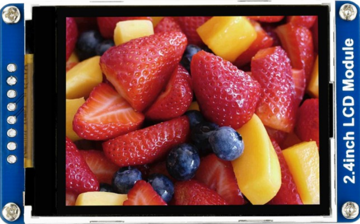
The 2.4" LCD Module featuring the ILI9341 controller is a popular display choice for a wide range of electronic projects. This compact and versatile module is capable of rendering colorful graphics and text, making it suitable for user interfaces, data visualization, and dynamic content display. Common applications include handheld devices, touch-screen interfaces, and embedded systems that require a visual output.
Explore Projects Built with 2.4" LCD Module


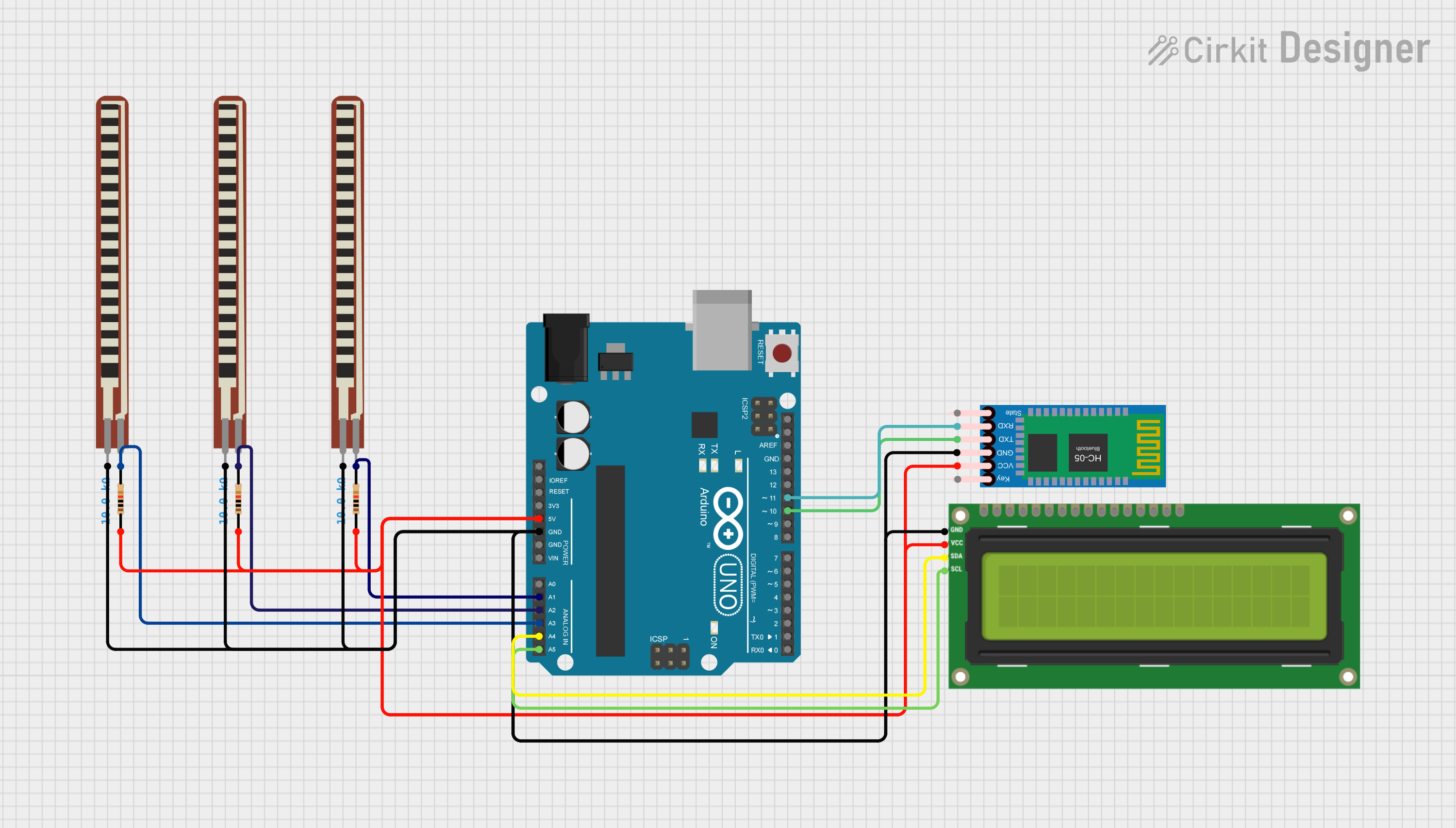

Explore Projects Built with 2.4" LCD Module
Technical Specifications
General Features
- Display Size: 2.4 inches
- Display Resolution: 240x320 pixels
- Interface: SPI (Serial Peripheral Interface)
- Controller: ILI9341
- Display Colors: 65K/262K
- Operating Voltage: 2.5V - 3.3V
- Logic Level: 3.3V (5V tolerant with level shifter)
Pin Configuration and Descriptions
| Pin Number | Pin Name | Description |
|---|---|---|
| 1 | VCC | Power supply (2.5V - 3.3V) |
| 2 | GND | Ground |
| 3 | CS | Chip Select |
| 4 | RESET | Reset signal (active low) |
| 5 | DC/RS | Data/Command control |
| 6 | SDI(MOSI) | Serial Data Input (Master Out Slave In) |
| 7 | SCK | Serial Clock Input |
| 8 | LED | Backlight control (anode) |
| 9 | SDO(MISO) | Serial Data Output (Master In Slave Out) |
Usage Instructions
Connecting to an Arduino UNO
Power Connections:
- Connect the VCC pin to the 3.3V output on the Arduino UNO.
- Connect the GND pin to one of the GND pins on the Arduino UNO.
Data Connections:
- Connect the CS pin to a digital pin (e.g., D10) on the Arduino UNO.
- Connect the RESET pin to a digital pin (e.g., D8).
- Connect the DC/RS pin to a digital pin (e.g., D9).
- Connect the SDI(MOSI) pin to the MOSI pin (D11) on the Arduino UNO.
- Connect the SCK pin to the SCK pin (D13) on the Arduino UNO.
- Connect the SDO(MISO) pin to the MISO pin (D12) on the Arduino UNO.
Backlight Connection:
- Connect the LED pin to a PWM-capable pin (e.g., D6) on the Arduino UNO for backlight control.
Arduino Code Example
#include <SPI.h>
#include <Adafruit_GFX.h>
#include <Adafruit_ILI9341.h>

// Pin configuration
#define TFT_CS     10
#define TFT_RST    8
#define TFT_DC     9

// Initialize Adafruit ILI9341
Adafruit_ILI9341 tft = Adafruit_ILI9341(TFT_CS, TFT_DC, TFT_RST);

void setup() {
  tft.begin();
  tft.setRotation(1); // Set rotation according to your setup
  tft.fillScreen(ILI9341_BLACK); // Clear the screen
}

void loop() {
  tft.setCursor(0, 0); // Set cursor at top-left corner
  tft.setTextColor(ILI9341_WHITE); // Set text color
  tft.setTextSize(1); // Set text size
  tft.println("Hello, World!"); // Print text to screen
}
Important Considerations and Best Practices
- Always ensure that the power supply voltage matches the module's requirements.
- Use a level shifter if you are interfacing with a 5V logic level device.
- Avoid exposing the display to direct sunlight or high temperatures to prevent damage.
- When handling the display, be cautious of static discharge and physical pressure on the screen.
Troubleshooting and FAQs
Common Issues
- Display Not Turning On: Check the power supply connections and ensure that the voltage is within the specified range.
- No Data on Display: Verify that the SPI connections are correct and that the correct pins are being used in your code.
- Distorted Images or Text: Ensure that the initialization sequence in your code matches the display's requirements.
FAQs
Q: Can I use this display with a 5V Arduino? A: Yes, but you will need to use a level shifter for the data lines to convert the 5V logic level to 3.3V.
Q: How can I control the backlight brightness?
A: You can control the backlight brightness by connecting the LED pin to a PWM-capable pin and using analogWrite() to adjust the duty cycle.
Q: What library should I use for this display? A: The Adafruit_ILI9341 library is recommended for this display, as it provides a wide range of functions for graphics and text.
Q: Can I use this display in outdoor environments? A: The display is not specifically designed for outdoor use and may be difficult to read in direct sunlight. Additionally, extreme temperatures can damage the display.
For further assistance, consult the manufacturer's datasheet and the community forums dedicated to the ILI9341 display module.