Cirkit Designer Logo
Cirkit Designer
Your all-in-one circuit design IDE
Home / 
Component Documentation

How to Use Adafruit 2x5 SWD Breakout: Examples, Pinouts, and Specs

Image of Adafruit 2x5 SWD Breakout
Cirkit Designer LogoDesign with Adafruit 2x5 SWD Breakout in Cirkit Designer

Introduction

The Adafruit 2x5 SWD Breakout is a specialized circuit component designed to facilitate the connection and programming of devices utilizing the Serial Wire Debug (SWD) interface. This breakout board is particularly useful for developers and engineers who need to interface with microcontrollers and development boards that support SWD, a two-wire protocol for accessing the debugging and programming features of ARM Cortex microcontrollers.

Explore Projects Built with Adafruit 2x5 SWD Breakout

Use Cirkit Designer to design, explore, and prototype these projects online. Some projects support real-time simulation. Click "Open Project" to start designing instantly!
Arduino UNO WiFi with Heart Pulse and Temperature Monitoring
Image of BioTrackers: A project utilizing Adafruit 2x5 SWD Breakout in a practical application
This circuit features an Arduino UNO R4 WiFi microcontroller connected to a Heart Pulse Sensor and an SHT1x-Breakout sensor. The Arduino is configured to read heart pulse signals from the Heart Pulse Sensor on analog pin A0 and temperature/humidity data from the SHT1x-Breakout sensor via the I2C interface on pins A4 (DATA) and A5 (SCK). Both sensors are powered by the Arduino's 5V output, and their ground pins are connected to the Arduino's ground.
Cirkit Designer LogoOpen Project in Cirkit Designer
Arduino Mega 2560-Based Real-Time Clock and Data Logging System with OLED Display
Image of projectwiring: A project utilizing Adafruit 2x5 SWD Breakout in a practical application
This circuit features an Arduino Mega 2560 microcontroller interfaced with an OLED display, a DS1307 RTC module, a microSD card breakout, a pushbutton, and a blue LED. The Arduino handles data logging to the microSD card, displays information on the OLED, and reads real-time data from the RTC module, while the pushbutton and LED provide user interaction and status indication.
Cirkit Designer LogoOpen Project in Cirkit Designer
Raspberry Pi-Controlled Dual Servo Driver with PCA9685 Interface
Image of Copy of PWM, SERVO, ESC Wiring: A project utilizing Adafruit 2x5 SWD Breakout in a practical application
This circuit controls two servomotors (MG996R and MG995) using a Raspberry Pi 5 and an Adafruit PCA9685 PWM Servo Breakout board. The Raspberry Pi communicates with the PCA9685 via I2C (using GPIO 2 and GPIO 3 for SDA and SCL, respectively) to send PWM signals to the servos. Power distribution is managed through an Adafruit Perma Proto Small Mint board, which connects the 5V and GND from the Raspberry Pi to the PCA9685 and the servos.
Cirkit Designer LogoOpen Project in Cirkit Designer
Arduino Mega ADK Automated Plant Watering and Environmental Monitoring System
Image of Automatisierungsprojekt Mega: A project utilizing Adafruit 2x5 SWD Breakout in a practical application
This circuit features an Arduino Mega ADK as the central microcontroller, interfacing with a variety of sensors and actuators. It includes a BH1750 light sensor and a DHT11 temperature and humidity sensor for environmental monitoring, both interfacing via I2C. The system controls a stepper motor via an A4988 driver, two water pumps through a 3-channel relay, and a fan using an IRF520 PWM module, with several push switches to trigger inputs. An OLED display provides a user interface, and soil moisture levels are monitored with two soil sensors. A non-contact water level sensor is also included for liquid level detection.
Cirkit Designer LogoOpen Project in Cirkit Designer

Explore Projects Built with Adafruit 2x5 SWD Breakout

Use Cirkit Designer to design, explore, and prototype these projects online. Some projects support real-time simulation. Click "Open Project" to start designing instantly!
Image of BioTrackers: A project utilizing Adafruit 2x5 SWD Breakout in a practical application
Arduino UNO WiFi with Heart Pulse and Temperature Monitoring
This circuit features an Arduino UNO R4 WiFi microcontroller connected to a Heart Pulse Sensor and an SHT1x-Breakout sensor. The Arduino is configured to read heart pulse signals from the Heart Pulse Sensor on analog pin A0 and temperature/humidity data from the SHT1x-Breakout sensor via the I2C interface on pins A4 (DATA) and A5 (SCK). Both sensors are powered by the Arduino's 5V output, and their ground pins are connected to the Arduino's ground.
Cirkit Designer LogoOpen Project in Cirkit Designer
Image of projectwiring: A project utilizing Adafruit 2x5 SWD Breakout in a practical application
Arduino Mega 2560-Based Real-Time Clock and Data Logging System with OLED Display
This circuit features an Arduino Mega 2560 microcontroller interfaced with an OLED display, a DS1307 RTC module, a microSD card breakout, a pushbutton, and a blue LED. The Arduino handles data logging to the microSD card, displays information on the OLED, and reads real-time data from the RTC module, while the pushbutton and LED provide user interaction and status indication.
Cirkit Designer LogoOpen Project in Cirkit Designer
Image of Copy of PWM, SERVO, ESC Wiring: A project utilizing Adafruit 2x5 SWD Breakout in a practical application
Raspberry Pi-Controlled Dual Servo Driver with PCA9685 Interface
This circuit controls two servomotors (MG996R and MG995) using a Raspberry Pi 5 and an Adafruit PCA9685 PWM Servo Breakout board. The Raspberry Pi communicates with the PCA9685 via I2C (using GPIO 2 and GPIO 3 for SDA and SCL, respectively) to send PWM signals to the servos. Power distribution is managed through an Adafruit Perma Proto Small Mint board, which connects the 5V and GND from the Raspberry Pi to the PCA9685 and the servos.
Cirkit Designer LogoOpen Project in Cirkit Designer
Image of Automatisierungsprojekt Mega: A project utilizing Adafruit 2x5 SWD Breakout in a practical application
Arduino Mega ADK Automated Plant Watering and Environmental Monitoring System
This circuit features an Arduino Mega ADK as the central microcontroller, interfacing with a variety of sensors and actuators. It includes a BH1750 light sensor and a DHT11 temperature and humidity sensor for environmental monitoring, both interfacing via I2C. The system controls a stepper motor via an A4988 driver, two water pumps through a 3-channel relay, and a fan using an IRF520 PWM module, with several push switches to trigger inputs. An OLED display provides a user interface, and soil moisture levels are monitored with two soil sensors. A non-contact water level sensor is also included for liquid level detection.
Cirkit Designer LogoOpen Project in Cirkit Designer

Common Applications and Use Cases

  • Debugging ARM Cortex microcontrollers
  • Programming microcontrollers without a dedicated programmer
  • Prototyping with development boards that lack onboard SWD connectors
  • Creating custom programming and debugging setups

Technical Specifications

Key Technical Details

  • Interface: Serial Wire Debug (SWD)
  • Pin Count: 10 pins (2x5 configuration)
  • Compatibility: Compatible with ARM Cortex microcontrollers and various development boards

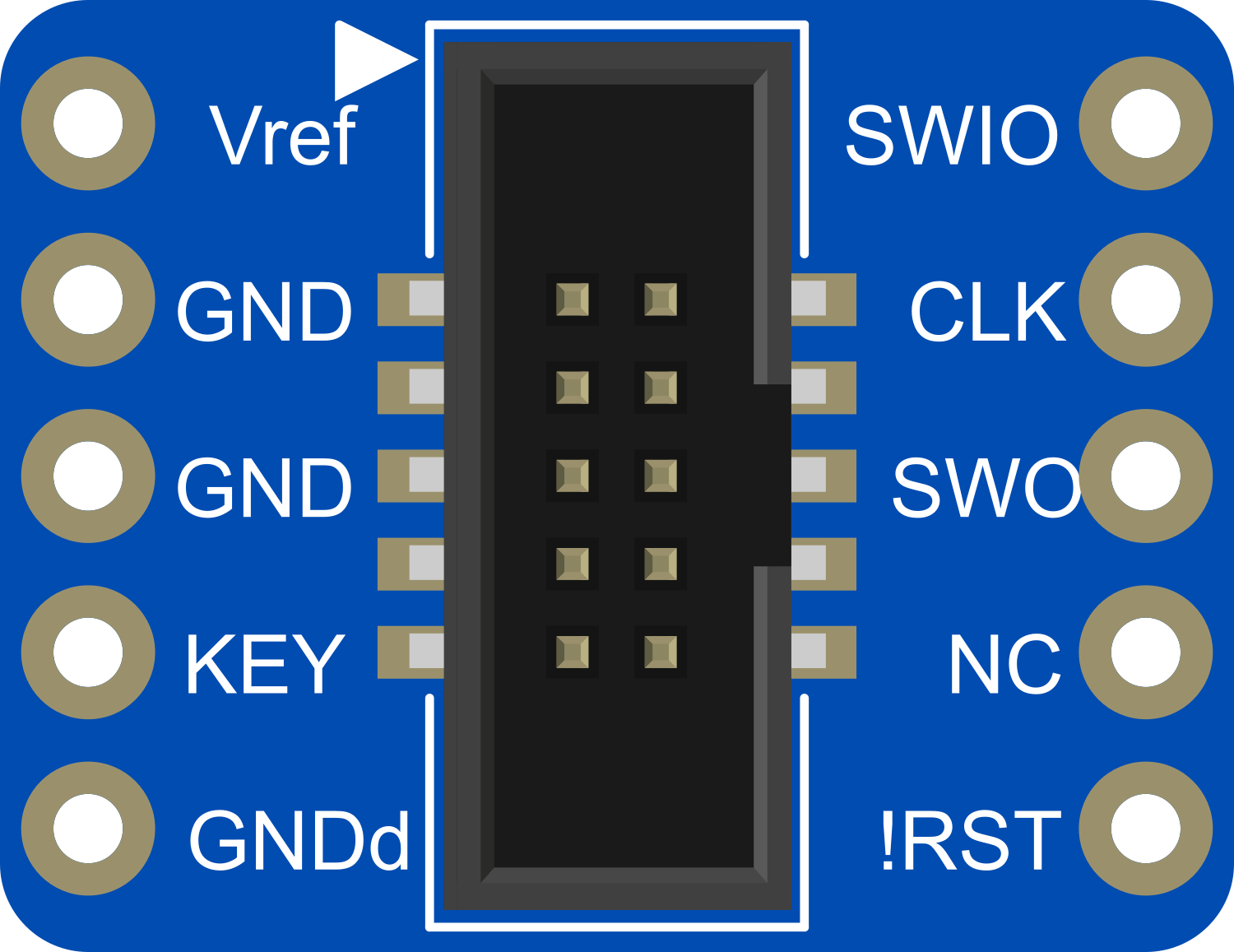
Pin Configuration and Descriptions

Pin Number Description Notes
1 VCC Power supply (3.3V typical)
2 SWDIO Serial Wire Debug I/O
3 SWCLK Serial Wire Debug Clock
4 GND Ground
5 GND Ground (optional for noise reduction)
6 SWO Serial Wire Output (optional)
7 Key No connection (for orientation)
8 NC No connection
9 NC No connection
10 RESET Reset signal (optional)

Usage Instructions

How to Use the Component in a Circuit

  1. Power Connection: Connect the VCC pin to a 3.3V power supply and the GND pin to the ground of your system.
  2. SWD Connection: Connect the SWDIO and SWCLK pins to the corresponding SWDIO and SWCLK pins on your target device.
  3. Optional Connections: If required, connect the SWO and RESET pins to the target device for additional debugging capabilities.

Important Considerations and Best Practices

  • Ensure that the power supply voltage matches the requirements of your target device to prevent damage.
  • Use short and direct connections between the breakout board and the target device to minimize signal integrity issues.
  • If your target device has a RESET pin, connecting it to the breakout board can be helpful for programming and debugging.
  • Always double-check the pin orientation before making connections to avoid incorrect wiring.

Troubleshooting and FAQs

Common Issues Users Might Face

  • Device Not Recognized: Ensure that all connections are secure and correctly oriented. Check the power supply and SWD interface for proper operation.
  • Noisy Signal: Use the additional GND pin for noise reduction if signal integrity issues are suspected.

Solutions and Tips for Troubleshooting

  • Check Connections: Verify that all cables and connections are secure and free from damage.
  • Power Cycle: Sometimes, simply power cycling the target device can resolve communication issues.
  • Signal Integrity: Keep the wires between the breakout board and the target device as short as possible to maintain signal integrity.

FAQs

Q: Can I use the Adafruit 2x5 SWD Breakout with a 5V system? A: No, the breakout is typically designed for 3.3V systems. Using it with a 5V system may damage the component or the target device.

Q: Is the Adafruit 2x5 SWD Breakout compatible with all ARM Cortex microcontrollers? A: It is compatible with most ARM Cortex microcontrollers that support the SWD protocol. However, always check the microcontroller's datasheet to ensure compatibility.

Q: Do I need to connect all the pins on the breakout board? A: No, only the VCC, GND, SWDIO, and SWCLK pins are essential for basic SWD communication. The SWO and RESET pins are optional and provide additional functionality.

Example Code for Arduino UNO

The Adafruit 2x5 SWD Breakout is not directly used with an Arduino UNO for programming, as the UNO does not typically serve as a SWD programmer. However, if you are using an Arduino-compatible board with an ARM Cortex microcontroller that supports SWD, you would use an external SWD programmer/debugger to interface with the breakout board.

// Example code is not applicable for Arduino UNO in the context of SWD programming.
// The Adafruit 2x5 SWD Breakout is used with external SWD programmers/debuggers.

For more specific examples and code related to using the Adafruit 2x5 SWD Breakout with compatible microcontrollers and programmers, please refer to the documentation of the SWD programmer/debugger you are using, as well as the microcontroller's datasheet and reference manual.