How to Use Fonte de alimentação: Examples, Pinouts, and Specs
Introduction
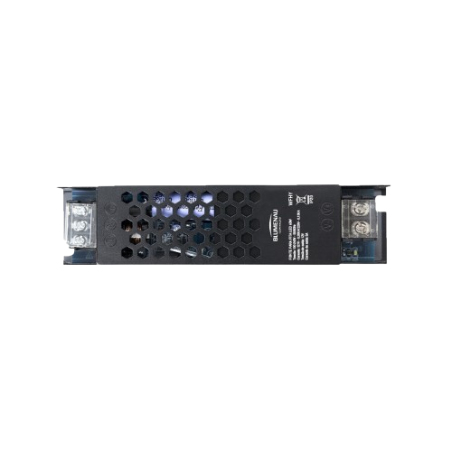
A Fonte de Alimentação (Power Supply Unit) is an essential electronic component that converts electrical energy from a source (e.g., AC mains or batteries) into a stable and usable form of power for electronic circuits. It ensures that connected devices receive the correct voltage and current required for their operation. Power supplies are available in various types, such as linear, switching, and programmable, to suit different applications.
Explore Projects Built with Fonte de alimentação
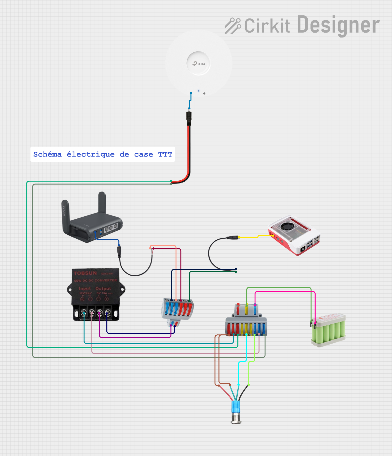


Explore Projects Built with Fonte de alimentação
Common Applications and Use Cases
- Powering microcontrollers, sensors, and actuators in embedded systems
- Supplying energy to industrial equipment and machinery
- Charging batteries and portable devices
- Providing stable voltage for laboratory testing and prototyping
- Supporting consumer electronics like televisions, computers, and audio systems
Technical Specifications
Below are the general technical specifications for a typical power supply unit. Specifications may vary depending on the specific model and type.
Key Technical Details
- Input Voltage: 100–240V AC (for AC-DC power supplies) or 12–24V DC (for DC-DC converters)
- Output Voltage: 3.3V, 5V, 12V, or adjustable (depending on the model)
- Output Current: 0.5A to 10A (or higher for high-power units)
- Power Rating: 5W to 500W (or more for industrial units)
- Efficiency: 70%–95% (higher for switching power supplies)
- Ripple and Noise: <50mV (for sensitive applications)
- Protection Features: Overvoltage, overcurrent, short-circuit, and thermal protection
Pin Configuration and Descriptions
The pin configuration of a power supply depends on its type. Below is an example of a DC-DC power supply module with adjustable output.
| Pin Name | Description |
|---|---|
| VIN | Input voltage pin (connect to the power source, e.g., 12V DC) |
| GND | Ground pin (common ground for input and output) |
| VOUT | Output voltage pin (provides the regulated voltage, e.g., 5V DC) |
| ADJ | Adjustment pin (used to set the output voltage, typically with a potentiometer) |
Usage Instructions
How to Use the Component in a Circuit
- Connect the Input Voltage:
- For AC-DC power supplies, connect the AC mains to the input terminals (L and N).
- For DC-DC converters, connect the input voltage to the VIN and GND pins.
- Set the Output Voltage (if adjustable):
- Use the adjustment pin (ADJ) or a built-in potentiometer to set the desired output voltage.
- Connect the Load:
- Attach the load (e.g., microcontroller, motor, or sensor) to the VOUT and GND pins.
- Verify Connections:
- Double-check all connections to ensure proper polarity and avoid short circuits.
- Power On:
- Turn on the power supply and measure the output voltage with a multimeter to confirm it matches the desired value.
Important Considerations and Best Practices
- Check the Ratings: Ensure the input voltage and current do not exceed the power supply's specifications.
- Use Proper Heat Dissipation: For high-power applications, ensure adequate cooling (e.g., heat sinks or fans).
- Avoid Overloading: Do not connect a load that exceeds the maximum output current.
- Use Fuses: Add fuses or circuit breakers to protect the power supply and connected devices.
- Minimize Noise: Use decoupling capacitors to reduce ripple and noise in sensitive circuits.
Example: Connecting to an Arduino UNO
A 5V DC power supply can be used to power an Arduino UNO. Below is an example of how to connect it and a simple Arduino sketch to blink an LED.
Circuit Connections
- Connect the VOUT pin of the power supply to the 5V pin on the Arduino UNO.
- Connect the GND pin of the power supply to the GND pin on the Arduino UNO.
- Connect an LED to pin 13 of the Arduino UNO with a 220-ohm resistor in series.
Arduino Code
// Simple LED Blink Example
// This code blinks an LED connected to pin 13 of the Arduino UNO.

void setup() {
  pinMode(13, OUTPUT); // Set pin 13 as an output pin
}

void loop() {
  digitalWrite(13, HIGH); // Turn the LED on
  delay(1000);            // Wait for 1 second
  digitalWrite(13, LOW);  // Turn the LED off
  delay(1000);            // Wait for 1 second
}
Troubleshooting and FAQs
Common Issues and Solutions
No Output Voltage:
- Check the input connections and ensure the power source is active.
- Verify that the input voltage is within the specified range.
- Inspect for blown fuses or tripped circuit breakers.
Output Voltage Too Low or Unstable:
- Ensure the load does not exceed the maximum current rating.
- Check for loose or corroded connections.
- If adjustable, reconfigure the output voltage using the adjustment pin or potentiometer.
Overheating:
- Ensure proper ventilation and cooling for the power supply.
- Reduce the load or use a higher-rated power supply.
Excessive Noise or Ripple:
- Add decoupling capacitors (e.g., 0.1µF and 10µF) near the load.
- Use shielded cables for sensitive applications.
FAQs
Q: Can I use a power supply with a higher current rating than my device requires?
A: Yes, as long as the voltage matches, the device will only draw the current it needs.
Q: How do I know if my power supply is overloaded?
A: Symptoms of overloading include voltage drops, overheating, or the power supply shutting down.
Q: Can I connect multiple devices to a single power supply?
A: Yes, but ensure the total current draw of all devices does not exceed the power supply's maximum current rating.
Q: What is the difference between linear and switching power supplies?
A: Linear power supplies are simpler and produce less noise but are less efficient. Switching power supplies are more efficient and compact but may introduce electrical noise.