How to Use SparkFun Qwiic Joystick: Examples, Pinouts, and Specs
Introduction
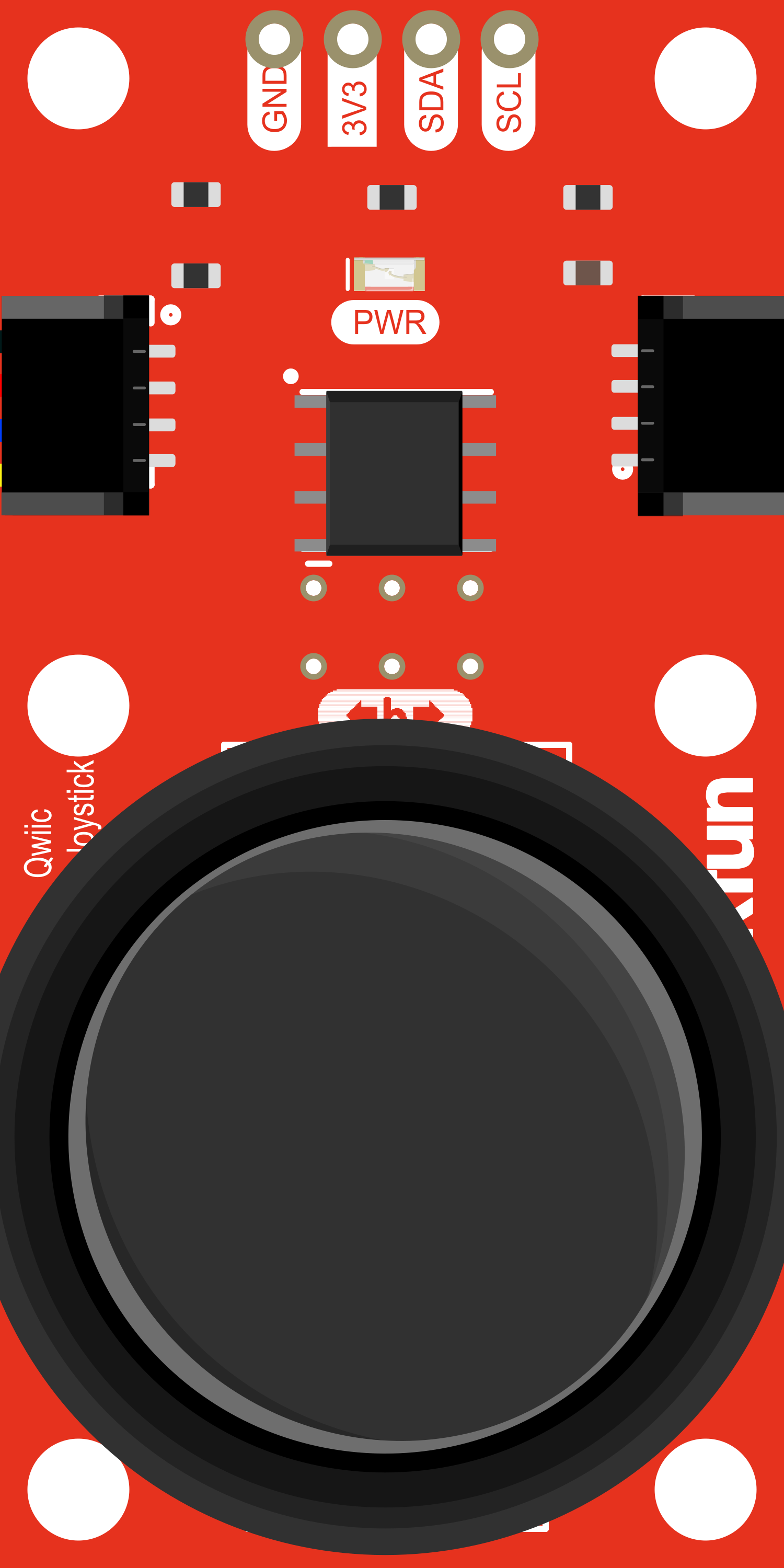
The SparkFun Qwiic Joystick is a compact breakout board that provides an intuitive interface for user input. It combines an analog joystick with two buttons, offering a simple yet effective control mechanism for a wide range of applications, from gaming controllers to robotic control systems. The integration of Qwiic connectors simplifies the process of connecting the joystick to other devices, enabling a quick and secure setup without the need for soldering.
Explore Projects Built with SparkFun Qwiic Joystick

Explore Projects Built with SparkFun Qwiic Joystick
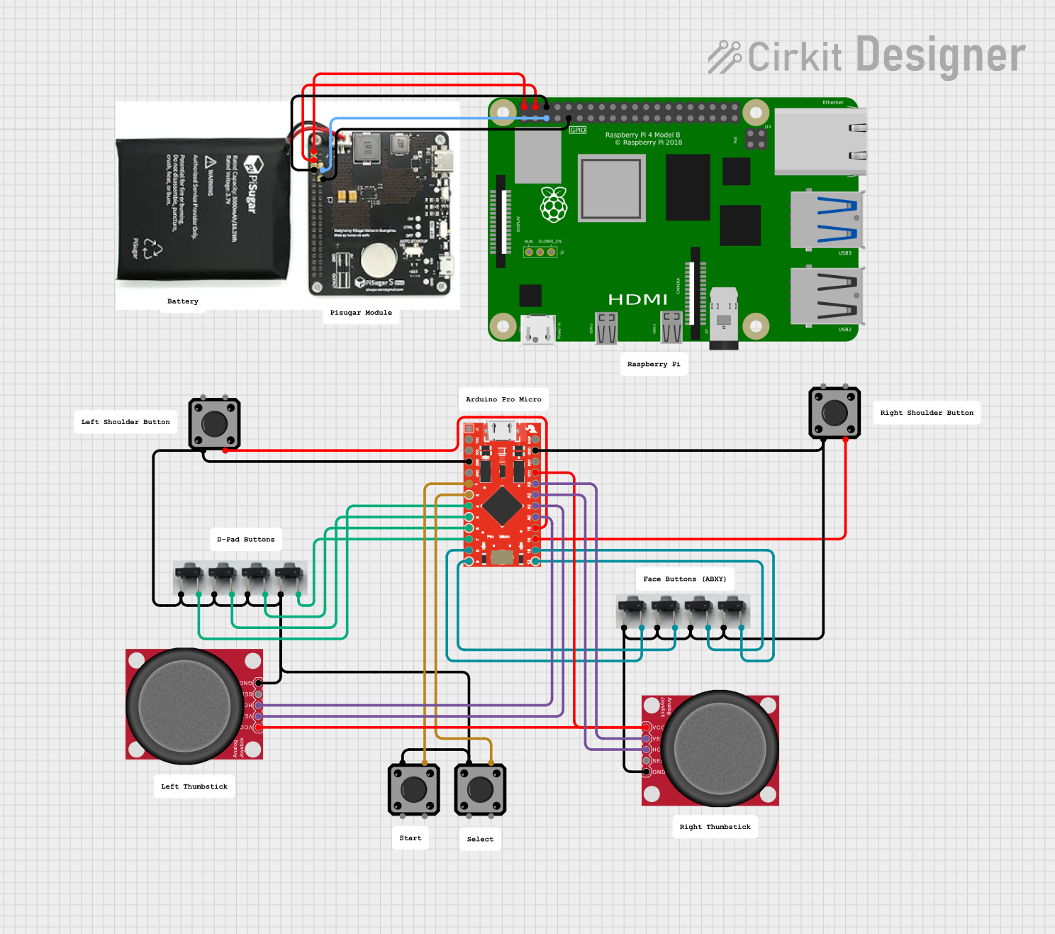
Common Applications
- Gaming controllers
- Robotics control interfaces
- Menu navigation for small displays
- DIY remote controls for various projects
Technical Specifications
Key Technical Details
- Voltage: 3.3V (via Qwiic connect system)
- Current: 10 mA (typical use)
- Dimensions: 26.4mm x 26.4mm x 32mm
Pin Configuration and Descriptions
| Pin Name | Description |
|---|---|
| GND | Ground connection |
| 3.3V | Power supply input (3.3V from Qwiic system) |
| SDA | I2C data line |
| SCL | I2C clock line |
| INT | Interrupt pin (active low) |
Usage Instructions
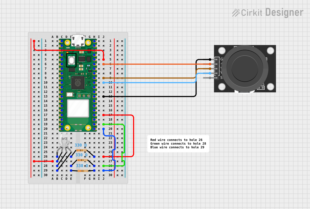
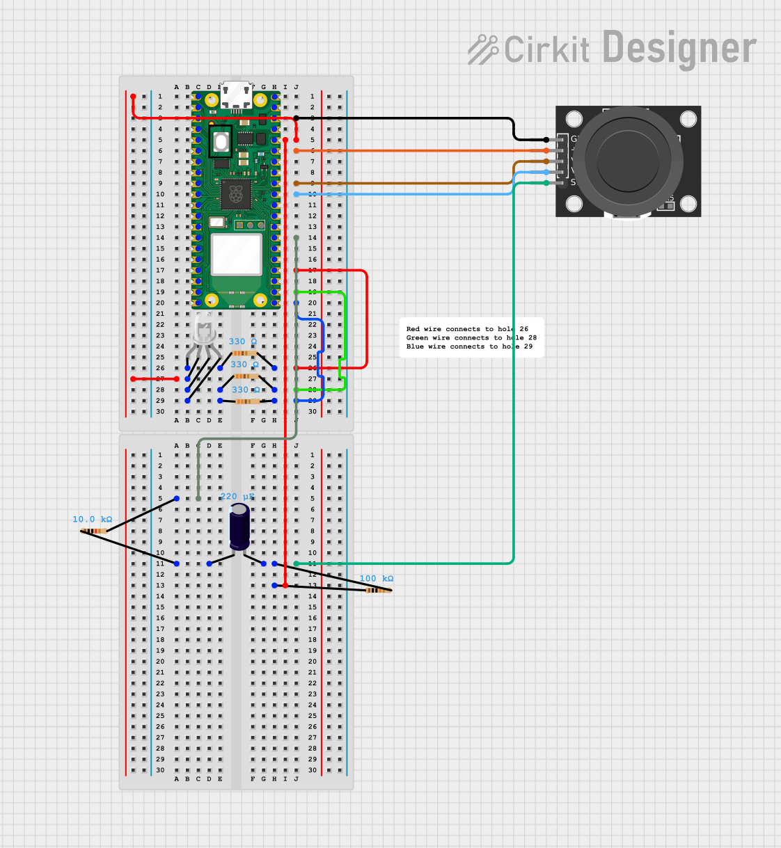
Integration into a Circuit
- Powering the Device: Connect the Qwiic Joystick to a 3.3V power source through the Qwiic connect system.
- I2C Communication: Utilize the SDA and SCL lines for I2C communication with your microcontroller.
- Mounting: Secure the joystick in your design, ensuring that it is accessible and can move freely.
Important Considerations and Best Practices
- Voltage Levels: Ensure that the power supply is 3.3V, as higher voltages may damage the board.
- I2C Addressing: The default I2C address for the Qwiic Joystick is 0x20. Make sure that no other device on the I2C bus has the same address.
- Calibration: Calibrate the joystick's center position in your software to account for any mechanical tolerances.
- Debouncing: Implement software debouncing for the buttons to prevent false triggering due to mechanical contact bounce.
Example Code for Arduino UNO
#include <Wire.h> // Include the I2C library (required for Qwiic)

// Define the I2C address for the Qwiic Joystick
#define JOYSTICK_ADDR 0x20

void setup() {
  Wire.begin(); // Join the I2C bus as a master
  Serial.begin(9600); // Start the serial communication
}

void loop() {
  Wire.beginTransmission(JOYSTICK_ADDR); // Start I2C transmission
  Wire.write(0x03); // Point to the specified register
  Wire.endTransmission(false); // End transmission, but keep the connection active

  Wire.requestFrom(JOYSTICK_ADDR, 5); // Request 5 bytes from the joystick
  while (Wire.available()) { // While bytes are available to read
    int joystickX = Wire.read(); // Read the X-axis value
    int joystickY = Wire.read(); // Read the Y-axis value
    int button1 = Wire.read(); // Read the button 1 value
    int button2 = Wire.read(); // Read the button 2 value
    // Print the values to the serial monitor
    Serial.print("X: ");
    Serial.print(joystickX);
    Serial.print(" Y: ");
    Serial.print(joystickY);
    Serial.print(" Button1: ");
    Serial.print(button1);
    Serial.print(" Button2: ");
    Serial.println(button2);
  }
  delay(500); // Wait for 500ms before the next loop iteration
}
Troubleshooting and FAQs
Common Issues
- Joystick Not Responding: Ensure that the Qwiic connections are secure and the power supply is at 3.3V.
- Inaccurate Readings: Calibrate the joystick's center position in your software.
- I2C Communication Errors: Check for conflicting I2C addresses and ensure proper pull-up resistors are in place.
Solutions and Tips for Troubleshooting
- Secure Connections: Double-check all Qwiic connectors and wiring to ensure a solid connection.
- Software Calibration: Implement a calibration routine in your setup code to account for any offset in the joystick's neutral position.
- I2C Scanning: Use an I2C scanning script to detect all devices on the bus and resolve any address conflicts.
FAQs
Q: Can I use the Qwiic Joystick with a 5V system? A: While the Qwiic system is designed for 3.3V, level shifting can be used to interface with 5V systems. However, direct connection without level shifting will damage the board.
Q: How do I change the I2C address of the joystick? A: The I2C address is fixed and cannot be changed for this device.
Q: Is it possible to use multiple Qwiic Joysticks on the same I2C bus? A: Since the I2C address is fixed, you cannot use multiple Qwiic Joysticks on the same bus without additional hardware, such as an I2C multiplexer.