How to Use MINIWIGGLER: Examples, Pinouts, and Specs
Introduction
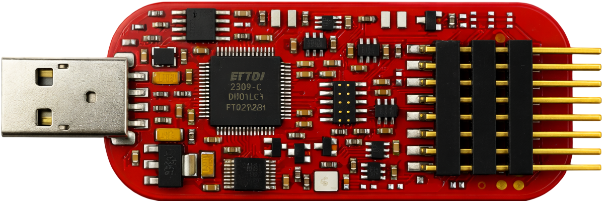
The MINIWIGGLER (Manufacturer Part ID: KIT_DAP_MINIWIGGLER_USB) by Infineon is a compact and versatile electronic device designed to generate low-frequency oscillations (LFOs) or modulations in signals. It is commonly used in audio applications to create effects such as vibrato, tremolo, and other signal modulations. Its small form factor and USB interface make it an ideal choice for developers and hobbyists working on audio signal processing or embedded systems.
Explore Projects Built with MINIWIGGLER


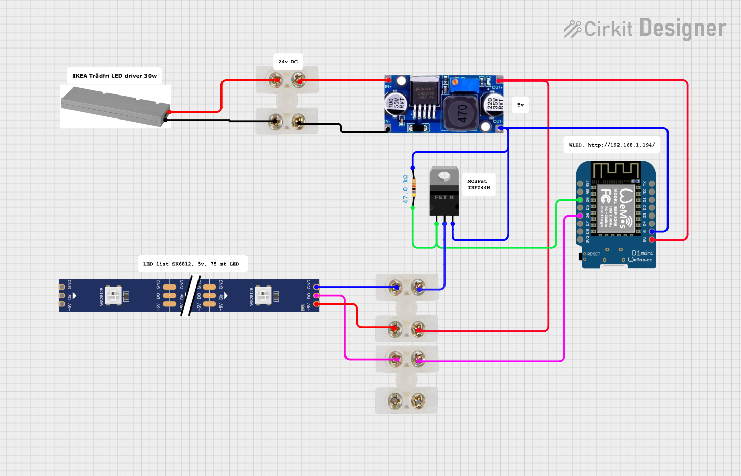
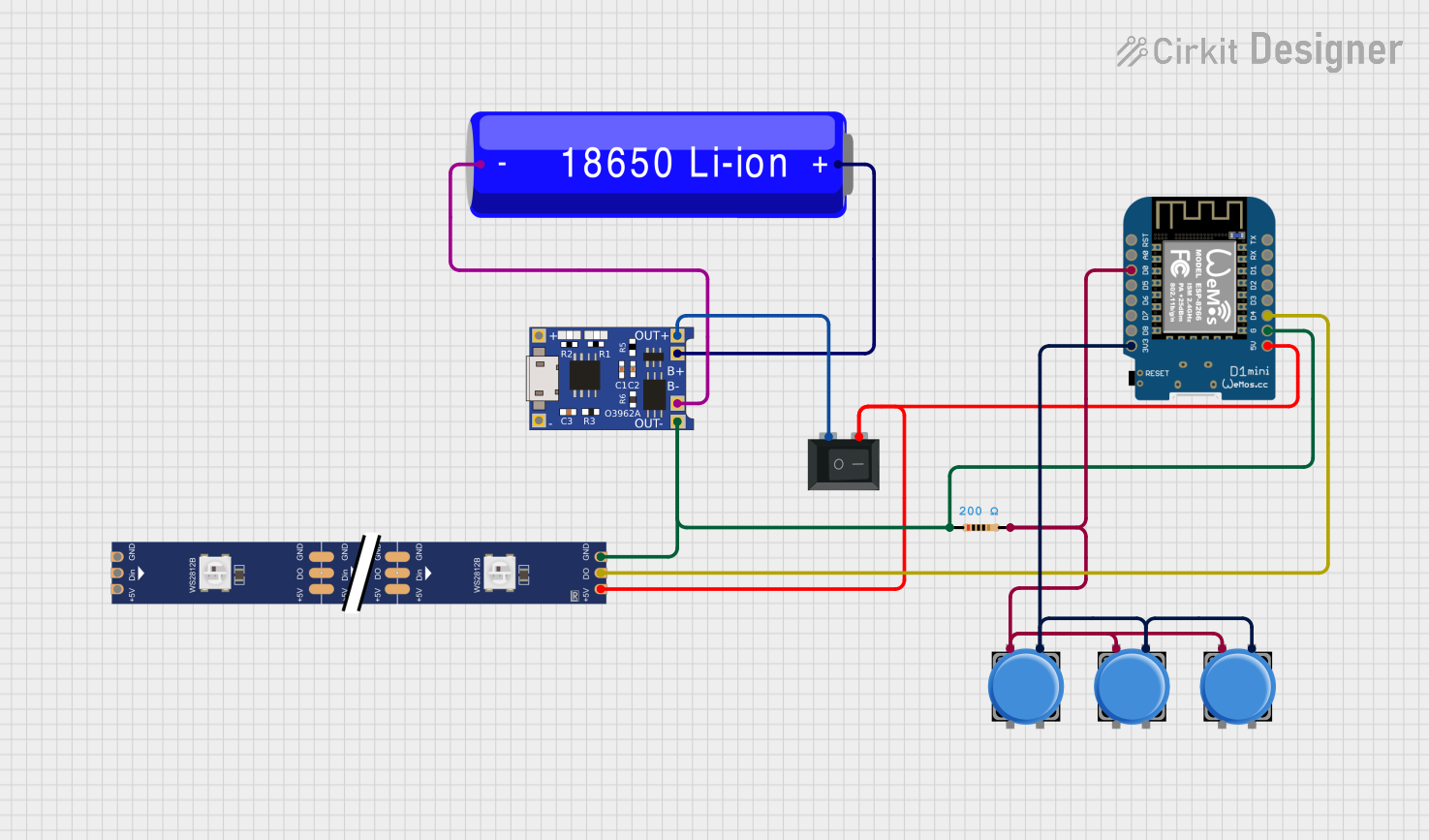
Explore Projects Built with MINIWIGGLER
Common Applications and Use Cases
- Audio signal modulation for vibrato, tremolo, or phasing effects
- Testing and debugging embedded systems with low-frequency signal generation
- Educational purposes for understanding signal modulation principles
- Integration into synthesizers or audio effect processors
Technical Specifications
Key Technical Details
| Parameter | Value |
|---|---|
| Manufacturer | Infineon |
| Part ID | KIT_DAP_MINIWIGGLER_USB |
| Power Supply Voltage | 5V (via USB) |
| Frequency Range | 0.1 Hz to 20 Hz |
| Output Signal Type | Sine, Square, and Triangle waves |
| Output Voltage Range | 0V to 3.3V |
| Communication Interface | USB 2.0 |
| Dimensions | 50mm x 25mm x 10mm |
| Operating Temperature | -40°C to +85°C |
Pin Configuration and Descriptions
The MINIWIGGLER has a USB interface for power and communication, along with a 6-pin header for signal output and debugging purposes.
| Pin Number | Pin Name | Description |
|---|---|---|
| 1 | VCC | 3.3V power output for external circuits |
| 2 | GND | Ground connection |
| 3 | SIGNAL_OUT | Modulated signal output (LFO) |
| 4 | DEBUG_CLK | Debug clock signal for embedded systems |
| 5 | DEBUG_DATA | Debug data signal for embedded systems |
| 6 | NC | Not connected |
Usage Instructions
How to Use the MINIWIGGLER in a Circuit
- Powering the Device: Connect the MINIWIGGLER to a USB port using a standard USB cable. This provides both power (5V) and communication capabilities.
- Signal Output: Use the
SIGNAL_OUTpin to connect the generated LFO signal to your target circuit. Ensure the target circuit can handle the 0V to 3.3V output range. - Debugging: For embedded system debugging, connect the
DEBUG_CLKandDEBUG_DATApins to the corresponding pins on your microcontroller or target device. - Waveform Selection: Use the provided software interface (available from Infineon) to select the desired waveform (sine, square, or triangle) and adjust the frequency.
Important Considerations and Best Practices
- Signal Integrity: Keep the signal output wire as short as possible to minimize noise and signal degradation.
- Power Supply: Ensure the USB port provides a stable 5V supply. Avoid using unregulated USB hubs.
- Frequency Range: The MINIWIGGLER is optimized for low-frequency applications (0.1 Hz to 20 Hz). Do not attempt to use it for high-frequency signal generation.
- Software Configuration: Download and install the Infineon software tools to configure the MINIWIGGLER. Follow the manufacturer's instructions for installation and usage.
Example: Using MINIWIGGLER with Arduino UNO
The MINIWIGGLER can be used to modulate an LED's brightness using its LFO signal. Below is an example Arduino sketch:
// Example: Using MINIWIGGLER to modulate LED brightness
// Connect SIGNAL_OUT from MINIWIGGLER to Arduino analog pin A0
// Connect an LED to pin 9 with a 220-ohm resistor

const int ledPin = 9;  // Pin connected to the LED
const int signalPin = A0;  // Pin connected to MINIWIGGLER SIGNAL_OUT

void setup() {
  pinMode(ledPin, OUTPUT);  // Set LED pin as output
  Serial.begin(9600);  // Initialize serial communication for debugging
}

void loop() {
  int signalValue = analogRead(signalPin);  // Read LFO signal from MINIWIGGLER
  int pwmValue = map(signalValue, 0, 1023, 0, 255);
  // Map the analog signal (0-1023) to PWM range (0-255)

  analogWrite(ledPin, pwmValue);  // Set LED brightness based on LFO signal
  delay(10);  // Small delay for stability
}
Troubleshooting and FAQs
Common Issues and Solutions
No Signal Output:
- Ensure the MINIWIGGLER is properly connected to a USB port.
- Verify that the software configuration is correct and the desired waveform is selected.
- Check the
SIGNAL_OUTconnection for loose wires or shorts.
Signal Distortion:
- Use shielded cables for the
SIGNAL_OUTconnection to reduce noise. - Ensure the target circuit is not drawing excessive current from the
VCCpin.
- Use shielded cables for the
Device Not Recognized by Computer:
- Confirm that the USB cable is functional and properly connected.
- Install the latest drivers and software from Infineon's website.
Debugging Pins Not Working:
- Verify the connections to the
DEBUG_CLKandDEBUG_DATApins. - Ensure the target device is powered and configured for debugging.
- Verify the connections to the
FAQs
Q: Can the MINIWIGGLER generate high-frequency signals?
A: No, the MINIWIGGLER is designed for low-frequency oscillations (0.1 Hz to 20 Hz). For high-frequency applications, consider using a dedicated signal generator.
Q: Is the MINIWIGGLER compatible with all microcontrollers?
A: Yes, as long as the microcontroller supports 3.3V logic levels for signal input. Use level shifters if your microcontroller operates at a different voltage.
Q: Where can I download the configuration software?
A: The software can be downloaded from Infineon's official website under the product page for KIT_DAP_MINIWIGGLER_USB.
Q: Can I use the MINIWIGGLER without a computer?
A: Yes, the MINIWIGGLER can operate independently once configured, but a computer is required for initial setup and waveform selection.