How to Use Voltage Step down: Examples, Pinouts, and Specs
Introduction
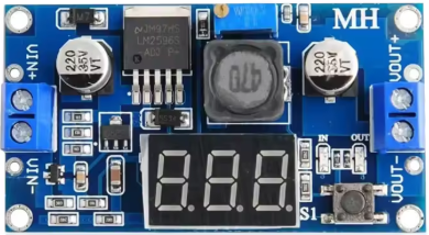
The Arduino ZX-052 Voltage Step Down, also known as a buck converter, is a highly efficient device designed to reduce a higher input voltage to a lower, stable output voltage. This component is widely used in power supply applications where precise voltage regulation is required, such as powering microcontrollers, sensors, and other low-voltage devices from higher voltage sources like batteries or solar panels.
Explore Projects Built with Voltage Step down


Explore Projects Built with Voltage Step down
Common Applications and Use Cases
- Powering Arduino boards and other microcontrollers from higher voltage sources
- Voltage regulation in battery-powered devices
- Solar power systems
- LED drivers
- Robotics and IoT projects requiring multiple voltage levels
Technical Specifications
The ZX-052 is designed to deliver reliable performance with the following specifications:
| Parameter | Value |
|---|---|
| Input Voltage Range | 6V to 36V |
| Output Voltage Range | 1.25V to 32V (adjustable) |
| Maximum Output Current | 3A (with proper heat dissipation) |
| Efficiency | Up to 92% |
| Switching Frequency | 150 kHz |
| Operating Temperature | -40°C to +85°C |
| Dimensions | 22mm x 17mm x 4mm |
Pin Configuration and Descriptions
The ZX-052 has the following pin layout:
| Pin Name | Description |
|---|---|
| VIN | Input voltage pin. Connect the higher voltage source (6V to 36V). |
| GND | Ground pin. Connect to the ground of the circuit. |
| VOUT | Output voltage pin. Provides the regulated lower voltage (1.25V to 32V). |
| ADJ | Adjustment pin. Use a potentiometer or resistor to set the desired output voltage. |
Usage Instructions
How to Use the ZX-052 in a Circuit
Connect the Input Voltage (VIN):
Attach the higher voltage source (e.g., a 12V battery) to the VIN pin. Ensure the input voltage is within the specified range (6V to 36V).Connect the Ground (GND):
Connect the GND pin to the ground of your circuit.Set the Output Voltage (VOUT):
- Use the onboard potentiometer to adjust the output voltage.
- Measure the output voltage using a multimeter while turning the potentiometer until the desired voltage is achieved.
Connect the Load:
Attach the device or circuit requiring the regulated voltage to the VOUT pin.Verify Connections:
Double-check all connections to ensure proper polarity and secure wiring.
Important Considerations and Best Practices
Heat Dissipation:
If the output current exceeds 2A, ensure proper heat dissipation by attaching a heatsink to the ZX-052 or using active cooling.Input Voltage:
Always ensure the input voltage is higher than the desired output voltage by at least 1.5V for proper operation.Output Voltage Adjustment:
Avoid turning the potentiometer too quickly or beyond its limits to prevent damage to the component.Capacitor Placement:
For stable operation, use input and output capacitors (e.g., 10µF to 100µF) close to the VIN and VOUT pins to reduce voltage ripple.
Example: Using ZX-052 with Arduino UNO
The ZX-052 can be used to power an Arduino UNO from a 12V battery by stepping down the voltage to 5V. Below is an example circuit and Arduino code:
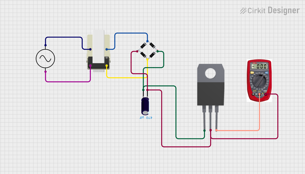
Circuit Connections
- Connect the 12V battery's positive terminal to the VIN pin of the ZX-052.
- Connect the battery's negative terminal to the GND pin of the ZX-052.
- Adjust the output voltage of the ZX-052 to 5V using the potentiometer.
- Connect the VOUT pin of the ZX-052 to the 5V pin of the Arduino UNO.
- Connect the GND pin of the ZX-052 to the GND pin of the Arduino UNO.
Arduino Code Example
// Example code to blink an LED using Arduino UNO powered by ZX-052
// Ensure the ZX-052 output is set to 5V before connecting to the Arduino UNO.

const int ledPin = 13; // Pin connected to the onboard LED

void setup() {
  pinMode(ledPin, OUTPUT); // Set the LED pin as an output
}

void loop() {
  digitalWrite(ledPin, HIGH); // Turn the LED on
  delay(1000);                // Wait for 1 second
  digitalWrite(ledPin, LOW);  // Turn the LED off
  delay(1000);                // Wait for 1 second
}
Troubleshooting and FAQs
Common Issues and Solutions
No Output Voltage:
- Cause: Incorrect wiring or insufficient input voltage.
- Solution: Verify all connections and ensure the input voltage is within the specified range.
Output Voltage Not Adjustable:
- Cause: Faulty potentiometer or incorrect adjustment.
- Solution: Check the potentiometer for damage and adjust it slowly while monitoring the output voltage.
Overheating:
- Cause: High output current without proper heat dissipation.
- Solution: Attach a heatsink or use active cooling to manage heat.
Voltage Ripple or Noise:
- Cause: Insufficient input/output capacitors.
- Solution: Add capacitors (10µF to 100µF) close to the VIN and VOUT pins.
FAQs
Q: Can the ZX-052 step up voltage?
A: No, the ZX-052 is a step-down (buck) converter and cannot increase the input voltage.
Q: What is the maximum current the ZX-052 can handle?
A: The ZX-052 can handle up to 3A with proper heat dissipation.
Q: Can I use the ZX-052 to power a 3.3V device?
A: Yes, adjust the output voltage to 3.3V using the potentiometer before connecting the device.
Q: Is the ZX-052 compatible with lithium-ion batteries?
A: Yes, as long as the battery voltage is within the input range (6V to 36V).
By following this documentation, users can effectively integrate the Arduino ZX-052 Voltage Step Down into their projects for efficient and reliable voltage regulation.