How to Use 8-channel I2C relay module: Examples, Pinouts, and Specs
Introduction
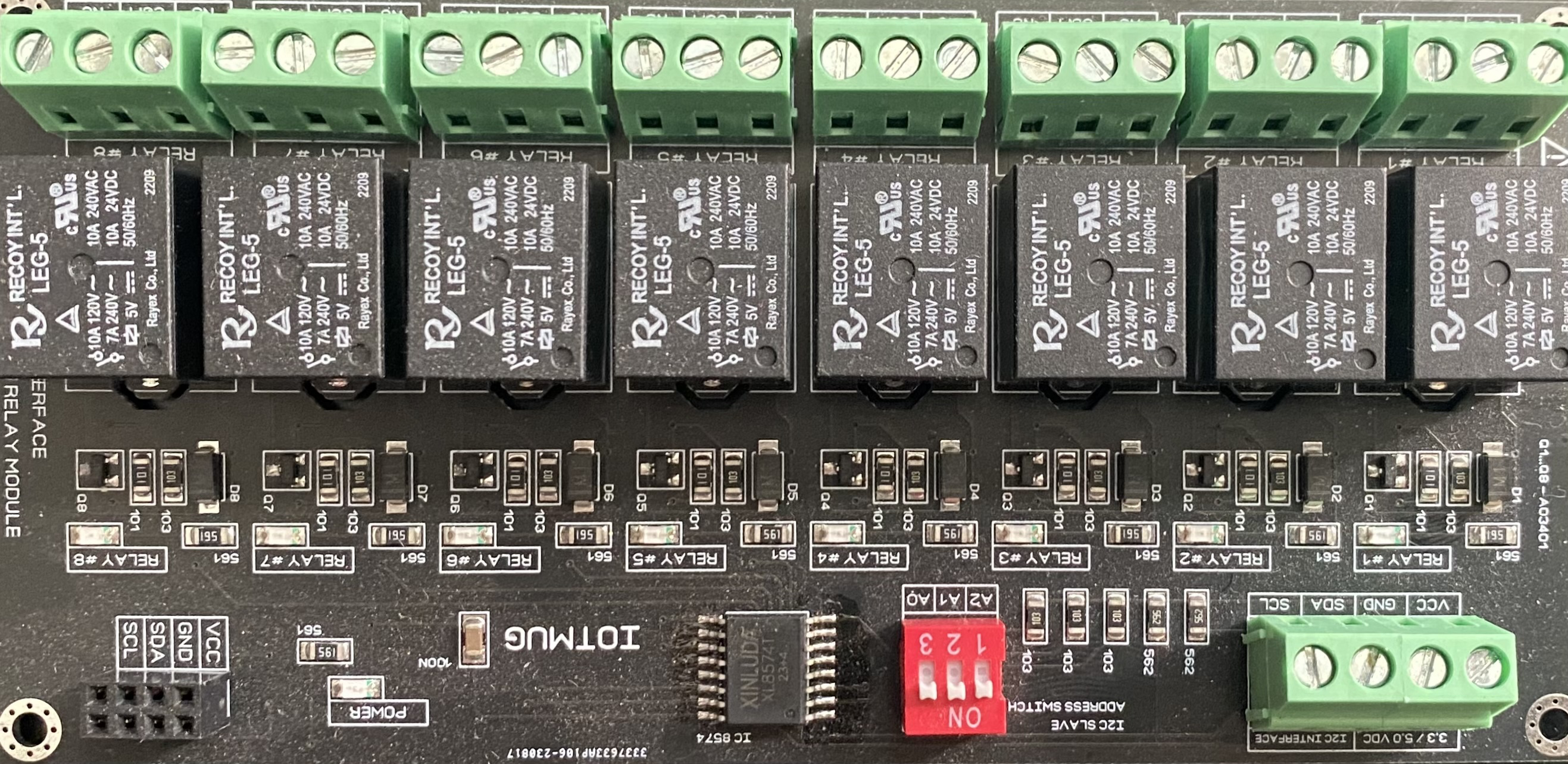
The 8-Channel I2C Relay Module by KRIDA is a versatile electronic component designed to control up to 8 relays using the I2C communication protocol. This module enables seamless integration with microcontrollers and single-board computers, allowing users to switch high-voltage devices (such as lights, fans, or appliances) using low-voltage control signals. Its compact design and I2C interface make it ideal for applications requiring multiple relay controls with minimal wiring.
Explore Projects Built with 8-channel I2C relay module


Explore Projects Built with 8-channel I2C relay module
Common Applications and Use Cases
- Home automation systems
- Industrial equipment control
- Robotics and IoT projects
- Smart lighting systems
- Prototyping and testing high-voltage circuits
Technical Specifications
The following table outlines the key technical details of the 8-Channel I2C Relay Module:
| Parameter | Specification |
|---|---|
| Operating Voltage | 5V DC |
| Communication Protocol | I2C |
| Default I2C Address | 0x20 (configurable via jumpers) |
| Relay Channels | 8 |
| Relay Type | SPDT (Single Pole Double Throw) |
| Maximum Relay Voltage | 250V AC / 30V DC |
| Maximum Relay Current | 10A |
| Power Consumption | ~300mA (all relays active) |
| Dimensions | 135mm x 55mm x 20mm |
Pin Configuration and Descriptions
The module has a set of pins for power, I2C communication, and relay outputs. Below is the pin configuration:
Power and Communication Pins
| Pin Name | Description |
|---|---|
| VCC | 5V DC power supply input |
| GND | Ground connection |
| SDA | I2C data line |
| SCL | I2C clock line |
Relay Output Terminals
Each relay has three terminals: COM, NO, and NC. These are used to connect the high-voltage devices.
| Terminal | Description |
|---|---|
| COM | Common terminal for the relay |
| NO | Normally Open terminal (connected when relay is active) |
| NC | Normally Closed terminal (connected when relay is inactive) |
Usage Instructions
How to Use the Module in a Circuit
- Power the Module: Connect the VCC and GND pins to a 5V DC power source.
- Connect to a Microcontroller: Use the SDA and SCL pins to connect the module to the I2C bus of your microcontroller (e.g., Arduino UNO).
- Configure the I2C Address: If using multiple modules, adjust the I2C address using the onboard jumpers.
- Connect High-Voltage Devices: Wire the devices to the relay terminals (COM, NO, NC) as per your switching requirements.
- Control the Relays: Use I2C commands to activate or deactivate the relays.
Important Considerations and Best Practices
- Ensure the total current drawn by the relays does not exceed the power supply's capacity.
- Use proper insulation and safety precautions when working with high-voltage devices.
- Avoid switching inductive loads (e.g., motors) without proper flyback diodes or snubber circuits to protect the relays.
- Verify the I2C address of the module to avoid conflicts with other devices on the same bus.
Example Code for Arduino UNO
Below is an example code snippet to control the 8-Channel I2C Relay Module using an Arduino UNO:
#include <Wire.h> // Include the Wire library for I2C communication

#define RELAY_MODULE_ADDR 0x20 // Default I2C address of the relay module

void setup() {
  Wire.begin(); // Initialize I2C communication
  Serial.begin(9600); // Initialize serial communication for debugging

  // Turn off all relays at startup
  Wire.beginTransmission(RELAY_MODULE_ADDR);
  Wire.write(0x00); // Send command to turn off all relays
  Wire.endTransmission();
  Serial.println("Relay module initialized. All relays are OFF.");
}

void loop() {
  // Example: Turn on relay 1
  Wire.beginTransmission(RELAY_MODULE_ADDR);
  Wire.write(0x01); // Send command to turn on relay 1
  Wire.endTransmission();
  Serial.println("Relay 1 is ON.");
  delay(2000); // Wait for 2 seconds

  // Example: Turn off relay 1
  Wire.beginTransmission(RELAY_MODULE_ADDR);
  Wire.write(0x00); // Send command to turn off relay 1
  Wire.endTransmission();
  Serial.println("Relay 1 is OFF.");
  delay(2000); // Wait for 2 seconds
}
Troubleshooting and FAQs
Common Issues and Solutions
Relays Not Responding
- Cause: Incorrect I2C address or wiring.
- Solution: Verify the I2C address and ensure proper connections for SDA, SCL, VCC, and GND.
High-Voltage Device Not Switching
- Cause: Incorrect wiring to the relay terminals.
- Solution: Double-check the connections to COM, NO, and NC based on your switching requirements.
Module Overheating
- Cause: Exceeding the maximum current or voltage ratings.
- Solution: Ensure the connected devices are within the relay's rated specifications.
I2C Communication Errors
- Cause: Conflicts with other devices on the I2C bus.
- Solution: Change the module's I2C address using the onboard jumpers.
FAQs
Q: Can I use this module with a 3.3V microcontroller?
A: Yes, but you will need a level shifter for the I2C lines, as the module operates at 5V.
Q: How do I change the I2C address?
A: Adjust the onboard jumpers according to the address configuration table in the module's datasheet.
Q: Can I control multiple modules on the same I2C bus?
A: Yes, as long as each module has a unique I2C address.
Q: Is the module safe for inductive loads?
A: Yes, but you should use flyback diodes or snubber circuits to protect the relays from voltage spikes.