How to Use Gearmotor DC / Motorreductor : Examples, Pinouts, and Specs
Introduction
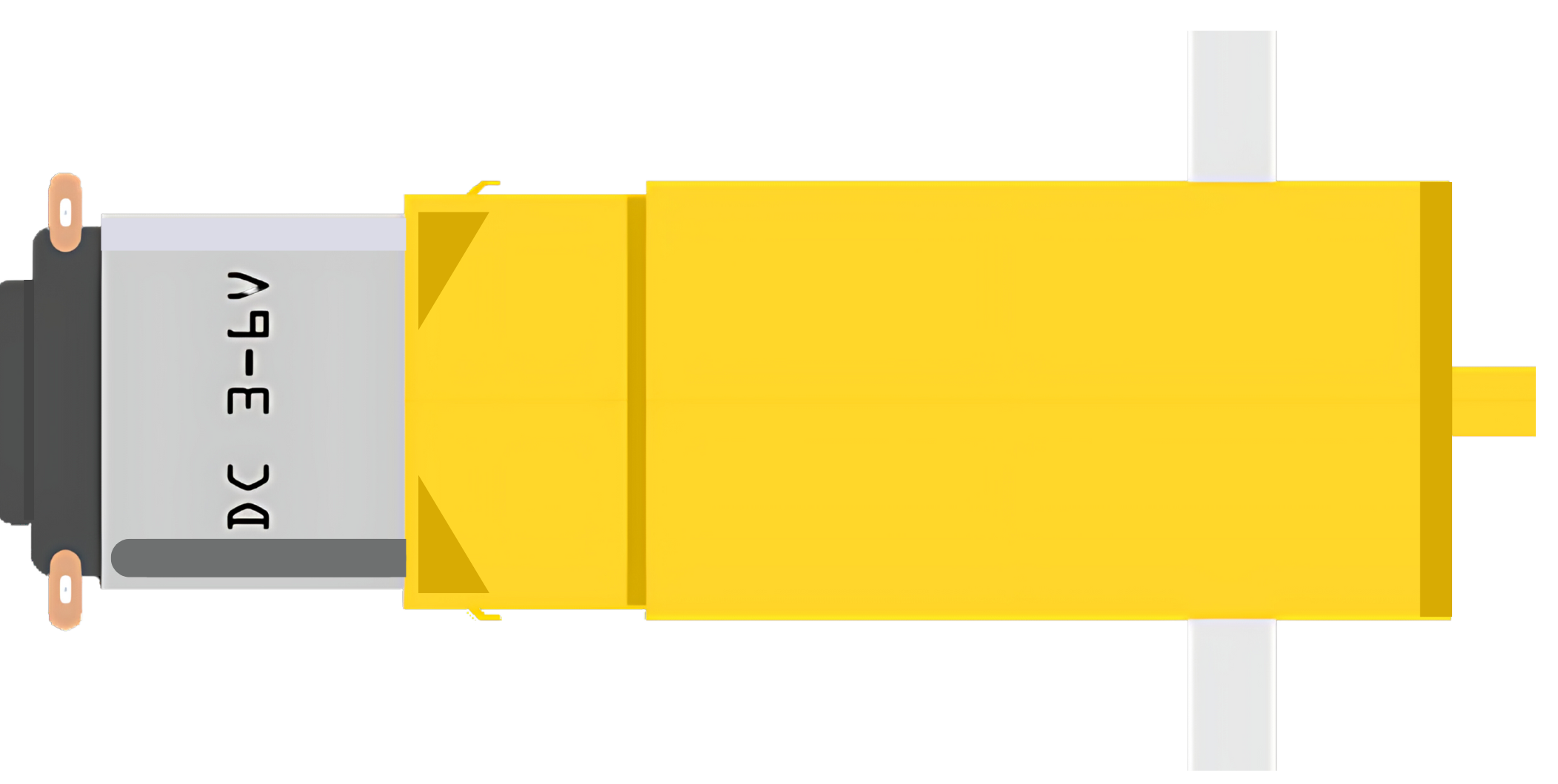
A Gearmotor DC, or Motorreductor, is an integrated device that combines a direct current (DC) electric motor with a gearbox to enhance torque while reducing speed. This combination allows for precise control of large loads at low speeds, making gearmotors ideal for a wide range of applications such as robotics, industrial machinery, automotive systems, and consumer electronics.
Explore Projects Built with Gearmotor DC / Motorreductor

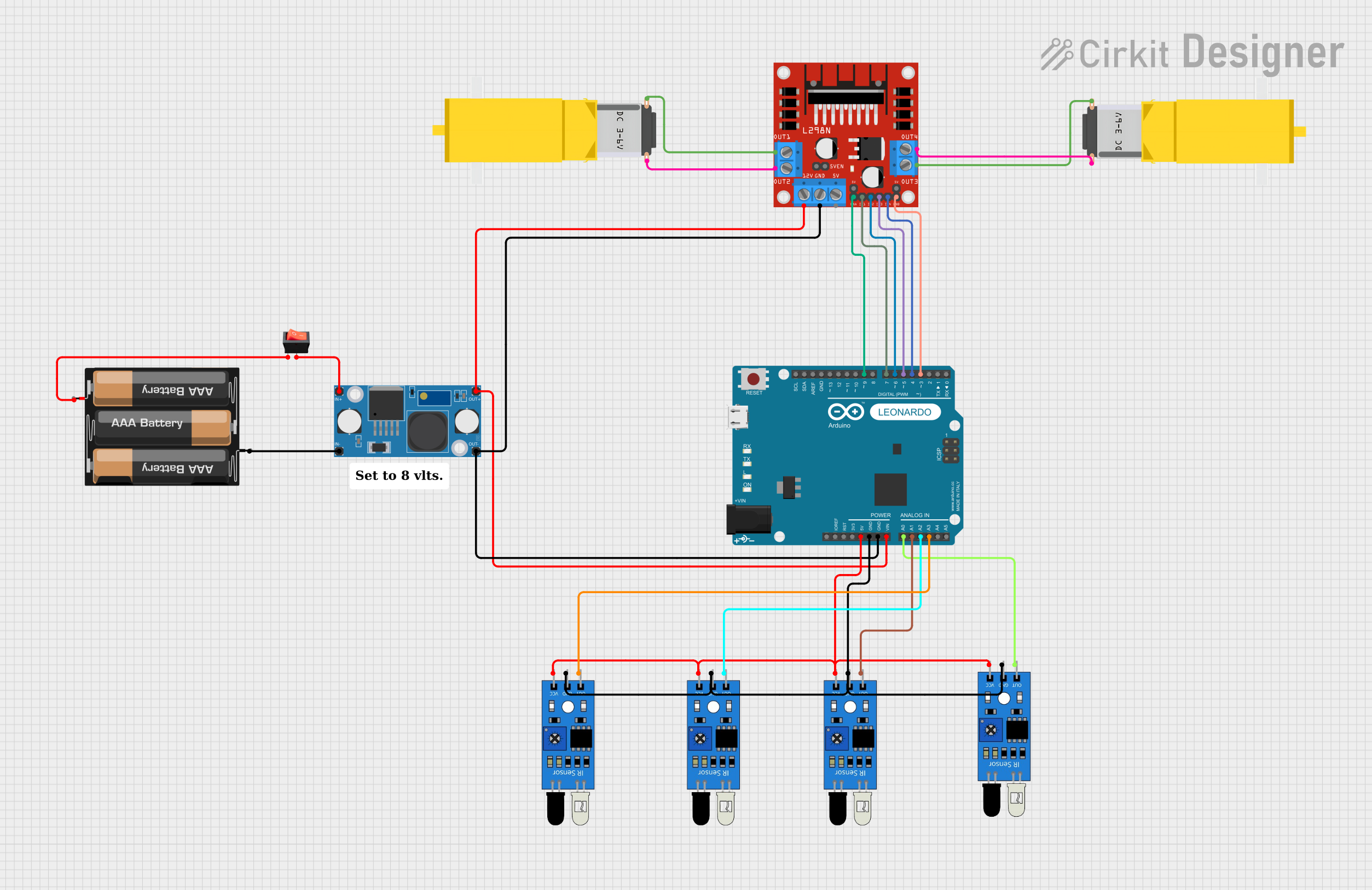
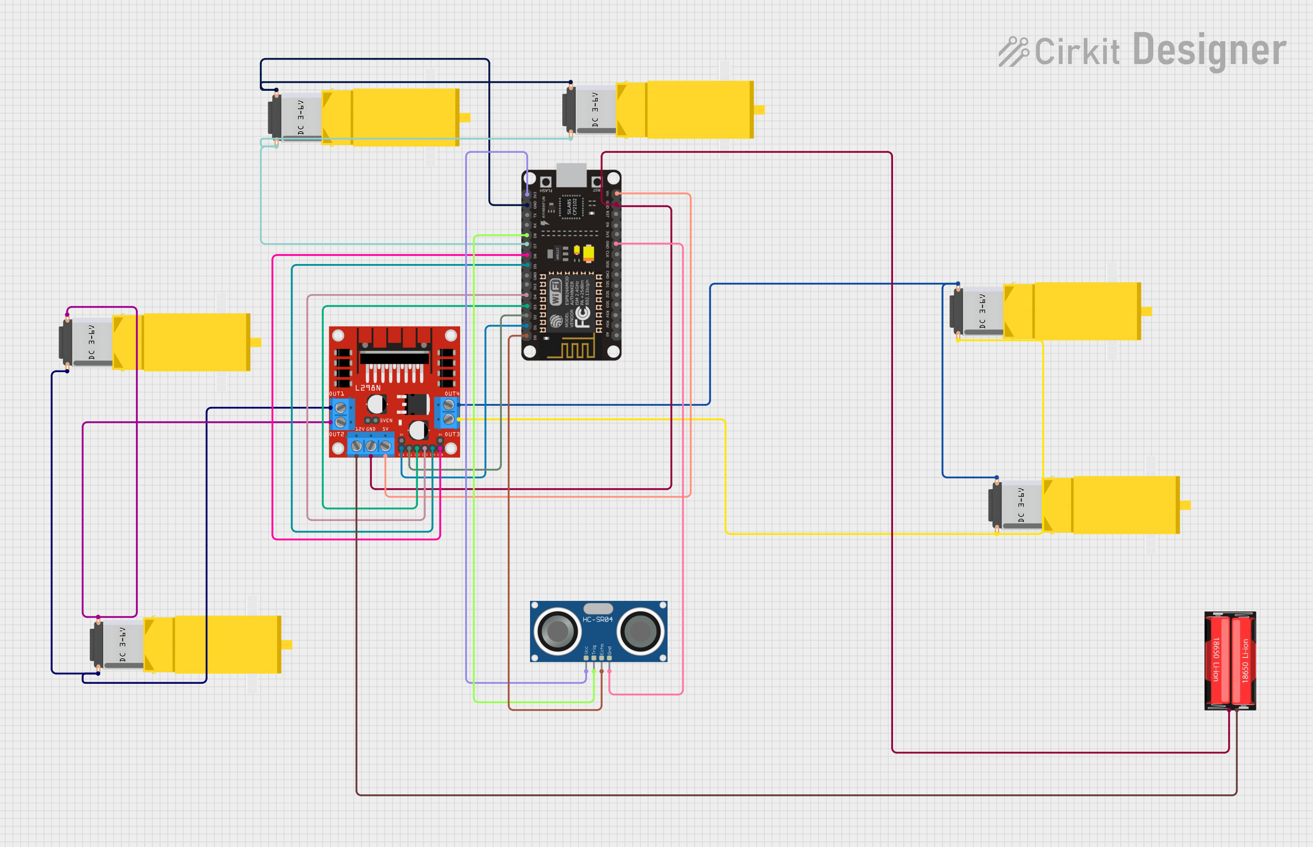
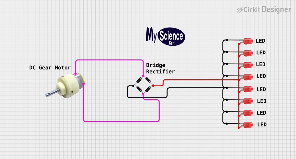
Explore Projects Built with Gearmotor DC / Motorreductor
Common Applications and Use Cases
- Robotics: Precise movement and positioning
- Automated machinery: Controlled operations requiring high torque
- Automotive: Electric window systems, seat adjustment
- Consumer electronics: Camera systems, smart home devices
Technical Specifications
Key Technical Details
- Voltage Range: Typically 3V to 24V DC
- Current Rating: Varies with model and load
- Power Output: Depends on gear ratio and motor efficiency
- Torque: Enhanced due to gear reduction
- Speed (RPM): Reduced proportionally to gear ratio
- Gear Ratio: Varies, common ratios include 10:1, 50:1, 100:1, etc.
- Efficiency: Dependent on gear type and quality
Pin Configuration and Descriptions
| Pin Number | Description | Notes |
|---|---|---|
| 1 | Motor Positive (+) | Connect to positive voltage |
| 2 | Motor Negative (-) | Connect to ground |
Usage Instructions
How to Use the Component in a Circuit
- Power Supply: Ensure that the power supply matches the voltage requirements of the gearmotor. Overvoltage can damage the motor, while undervoltage may result in insufficient performance.
- Motor Controller: Use a motor controller or H-bridge to control the direction and speed of the gearmotor.
- Load Considerations: Do not exceed the rated torque of the gearmotor as it can lead to gear failure or motor burnout.
Important Considerations and Best Practices
- Mounting: Securely mount the gearmotor to prevent misalignment of gears and potential damage.
- Lubrication: Ensure gears are properly lubricated to reduce wear and noise.
- Heat Dissipation: Provide adequate cooling if the motor is expected to operate continuously or under high load.
- Electrical Noise: Use appropriate filtering to minimize electrical noise, which can interfere with other electronics.
Troubleshooting and FAQs
Common Issues
- Motor not turning: Check power supply and connections. Ensure the motor controller is functioning correctly.
- Excessive noise or vibration: Inspect gears for wear or misalignment. Check if the motor is securely mounted.
- Overheating: Ensure the motor is not overloaded and has proper ventilation.
Solutions and Tips for Troubleshooting
- Intermittent Operation: Verify connections for any loose wires or poor solder joints.
- Reduced Torque: Check if the gearbox is clogged or requires lubrication.
- Direction Control Issues: Confirm that the motor controller or H-bridge is correctly programmed and wired.
Example Arduino UNO Code
// Example code to control a Gearmotor DC with an Arduino UNO
#include <Arduino.h>

const int motorPin1 = 3; // H-bridge leg 1 (pin 2, 1A)
const int motorPin2 = 4; // H-bridge leg 2 (pin 7, 2A)

void setup() {
  pinMode(motorPin1, OUTPUT);
  pinMode(motorPin2, OUTPUT);
}

void loop() {
  // Rotate motor in one direction
  digitalWrite(motorPin1, HIGH);
  digitalWrite(motorPin2, LOW);
  delay(1000);

  // Stop motor
  digitalWrite(motorPin1, LOW);
  digitalWrite(motorPin2, LOW);
  delay(1000);

  // Rotate motor in the opposite direction
  digitalWrite(motorPin1, LOW);
  digitalWrite(motorPin2, HIGH);
  delay(1000);

  // Stop motor
  digitalWrite(motorPin1, LOW);
  digitalWrite(motorPin2, LOW);
  delay(1000);
}
Note: This example assumes the use of an H-bridge for direction control. The motorPin1 and motorPin2 are connected to the H-bridge inputs, and the gearmotor is connected to the H-bridge outputs. Adjust the pin numbers and logic according to your specific H-bridge module and wiring. Always ensure that the power supply voltage and current are within the specifications of the gearmotor.