How to Use Solar Panel: Examples, Pinouts, and Specs
Introduction
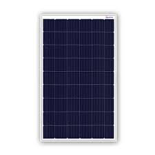
A solar panel is a device that converts sunlight into electrical energy through the photovoltaic effect. It consists of multiple solar cells made from semiconductor materials like silicon. When sunlight hits the solar cells, it excites electrons, creating an electric current. Solar panels are widely used in various applications, ranging from small-scale systems like solar-powered calculators and garden lights to large-scale solar farms that contribute to the electrical grid.
Explore Projects Built with Solar Panel
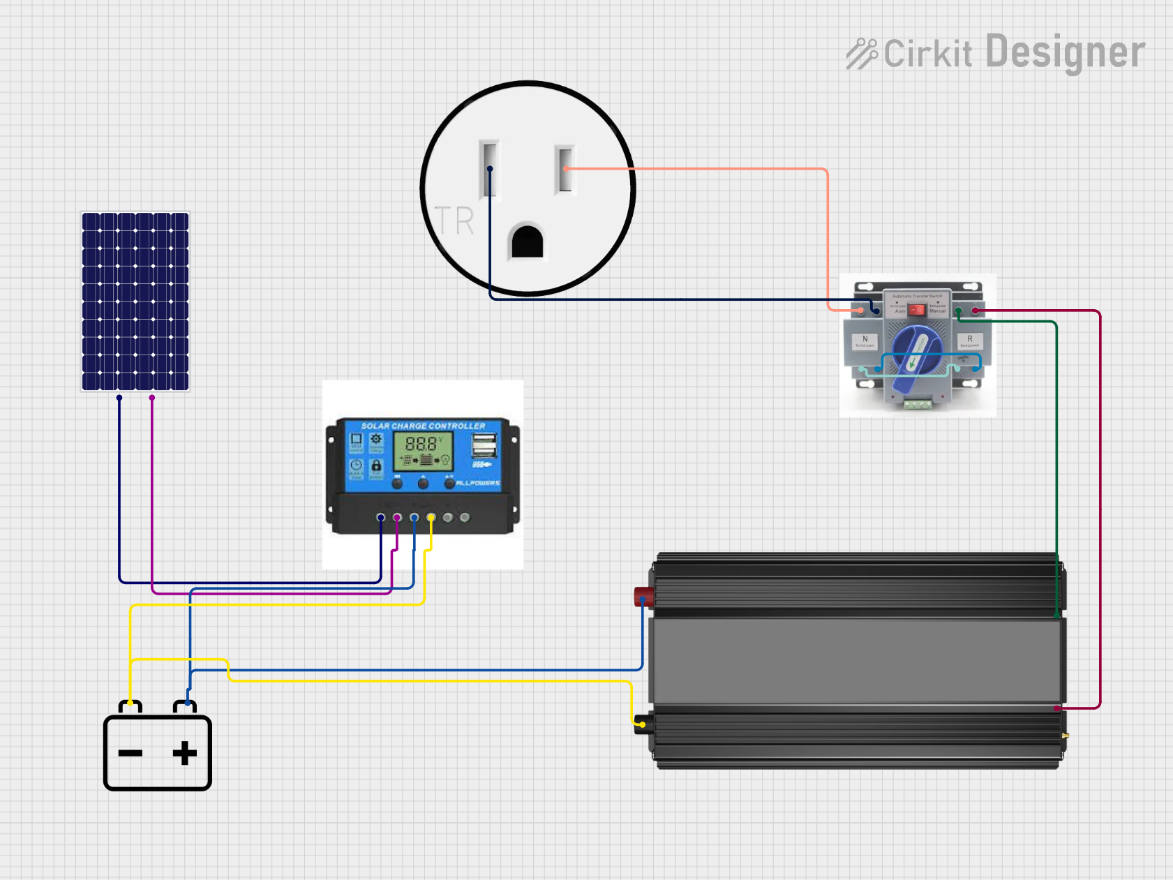
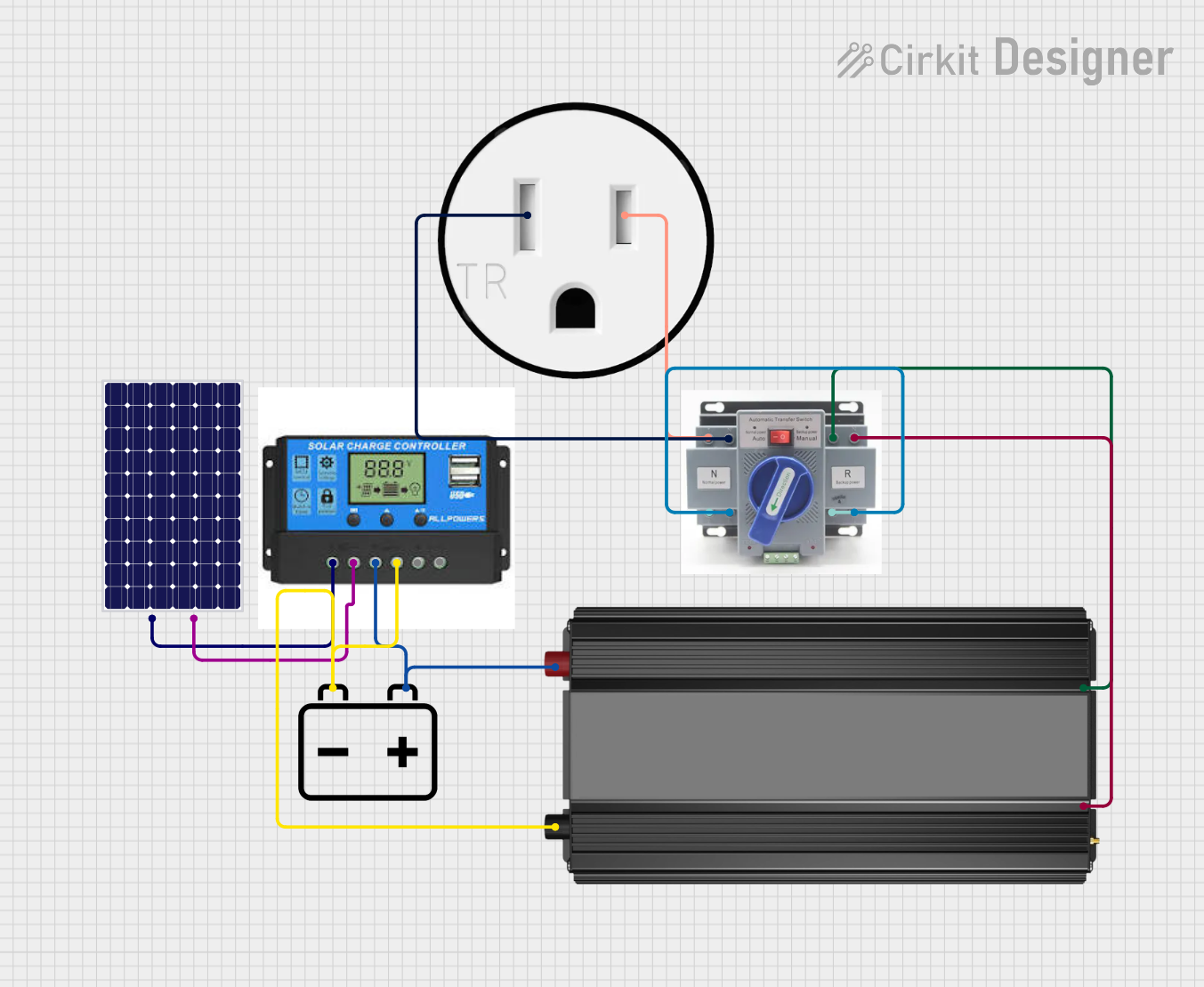

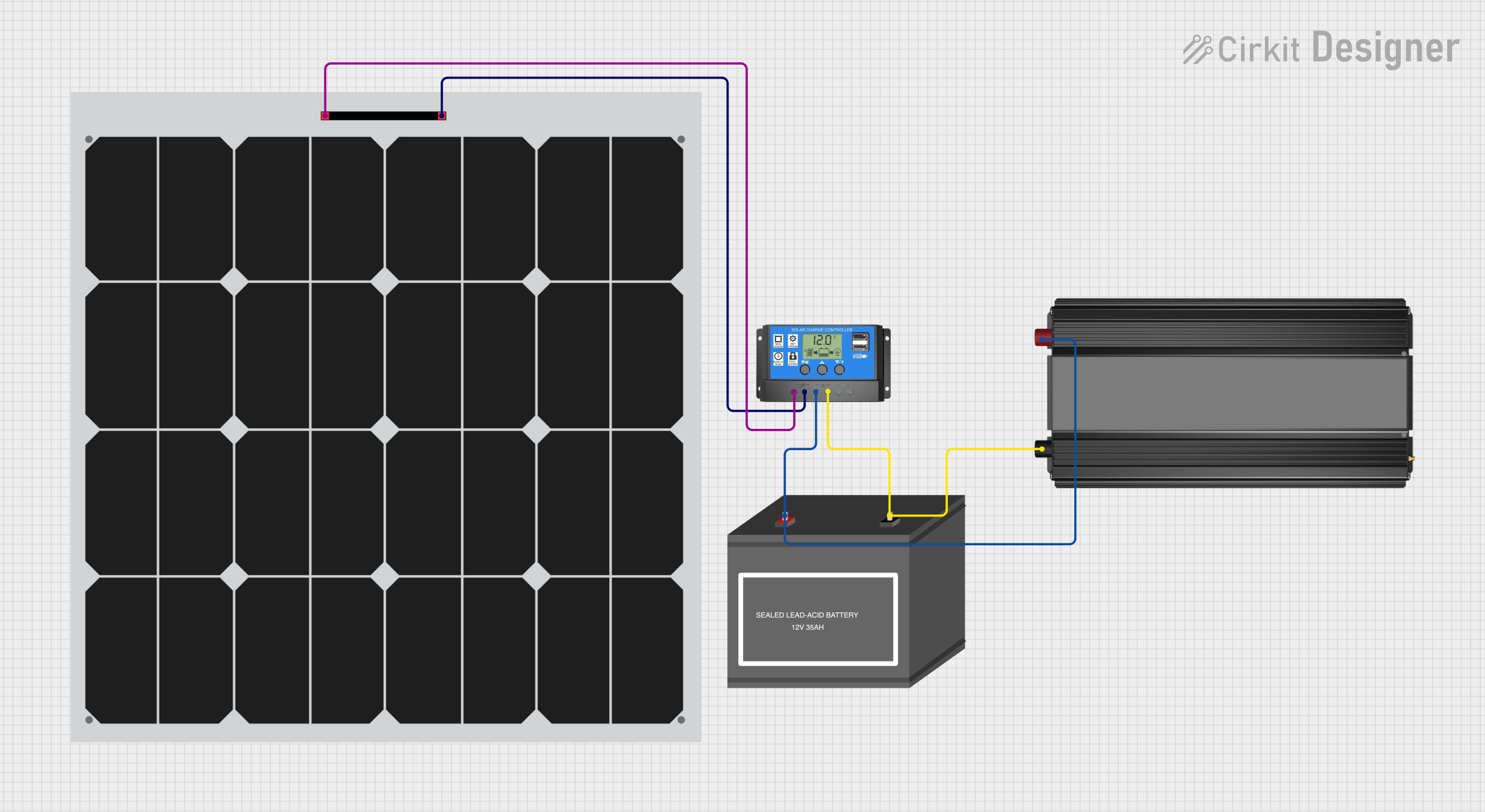
Explore Projects Built with Solar Panel
Common Applications and Use Cases
- Residential and commercial solar installations for electricity generation
- Portable solar chargers for electronic devices
- Solar-powered lighting systems
- Remote power systems for sensors and monitoring equipment
- Off-grid power solutions for cabins and recreational vehicles
Technical Specifications
Key Technical Details
| Specification | Description |
|---|---|
| Nominal Voltage | XX V |
| Operating Current | XX A |
| Maximum Power | XX W |
| Open Circuit Voltage (Voc) | XX V |
| Short Circuit Current (Isc) | XX A |
| Power Tolerance | ±XX% |
| Temperature Coefficient | XX%/°C |
| Dimensions | XX x XX x XX mm |
| Weight | XX kg |
Pin Configuration and Descriptions
| Pin Number | Description |
|---|---|
| 1 | Positive terminal (+) |
| 2 | Negative terminal (−) |
Usage Instructions
How to Use the Component in a Circuit
- Mounting the Solar Panel: Ensure the solar panel is mounted at an angle facing the sun for maximum exposure. The angle and direction depend on your geographical location.
- Wiring: Connect the positive terminal of the solar panel to the positive input of your charge controller, and the negative terminal to the negative input.
- Connecting to a Battery: The charge controller should be connected to a battery to store the electricity generated by the solar panel.
- Load Connection: Connect your load (e.g., lights, devices) to the output of the charge controller.
Important Considerations and Best Practices
- Orientation and Tilt: Position the solar panel to face true south (in the northern hemisphere) or true north (in the southern hemisphere) and adjust the tilt angle according to your latitude for optimal performance.
- Cleaning: Keep the surface of the solar panel clean to ensure maximum efficiency.
- Shading: Avoid any shading on the panel as this can significantly reduce power output.
- Ventilation: Ensure there is space behind the panel for air circulation to prevent overheating.
- Safety: Use appropriate safety equipment and procedures when installing and maintaining the solar panel.
Troubleshooting and FAQs
Common Issues Users Might Face
- Reduced Power Output: This can be due to shading, dirt accumulation on the panel, or a cloudy day.
- No Power Output: Check all connections, ensure the panel is exposed to sunlight, and verify that the charge controller and battery are functioning properly.
Solutions and Tips for Troubleshooting
- Cleaning: Regularly clean the panel surface with a soft cloth and soapy water to remove dirt and debris.
- Inspection: Periodically inspect the panel and wiring for any damage or wear.
- Professional Help: If you suspect a problem with the solar panel itself, such as damaged cells, seek professional assistance.
FAQs
Q: Can I connect multiple solar panels together? A: Yes, you can connect multiple panels in series to increase voltage or in parallel to increase current.
Q: Do solar panels work on cloudy days? A: Solar panels can still produce electricity on cloudy days, but their output will be reduced compared to sunny conditions.
Q: How long do solar panels last? A: Most solar panels are designed to last 25 years or more, but their efficiency may decrease gradually over time.
Q: Is a charge controller necessary? A: Yes, a charge controller is essential to protect the battery from overcharging and to regulate the power flow.
Q: Can I power my entire home with solar panels? A: It is possible to power a home with solar panels, but the number and size of the panels, as well as the availability of sunlight, will determine the feasibility.
Example Arduino UNO Code for Solar-Powered System
// This example assumes the use of a solar panel connected to a charge controller
// and a battery, which powers an Arduino UNO. The Arduino monitors the battery voltage.

const int batteryVoltagePin = A0; // Connect to the battery voltage through a voltage divider

void setup() {
  Serial.begin(9600);
}

void loop() {
  int sensorValue = analogRead(batteryVoltagePin);
  float batteryVoltage = sensorValue * (5.0 / 1023.0) * (11.0); // Adjust the multiplier (11.0) based on your voltage divider
  Serial.print("Battery Voltage: ");
  Serial.println(batteryVoltage);
  delay(1000); // Wait for 1 second before reading the voltage again
}
Note: The code above is a simple demonstration of how to monitor battery voltage with an Arduino. The actual implementation in a solar-powered project may vary based on specific requirements and additional components used. Always ensure that the voltage levels are safe for the Arduino's analog input pins by using an appropriate voltage divider or level-shifting circuit.