How to Use Arduino® Nano R4: Examples, Pinouts, and Specs
Introduction
The Arduino® Nano R4 (Manufacturer Part ID: ABX00142) is a compact and versatile microcontroller board designed for a wide range of applications. Based on the ATmega328P microcontroller, it features a small form factor, making it ideal for projects where space is limited. The Nano R4 offers both digital and analog input/output pins, USB connectivity, and seamless compatibility with the Arduino IDE, enabling easy programming and prototyping.
Explore Projects Built with Arduino® Nano R4
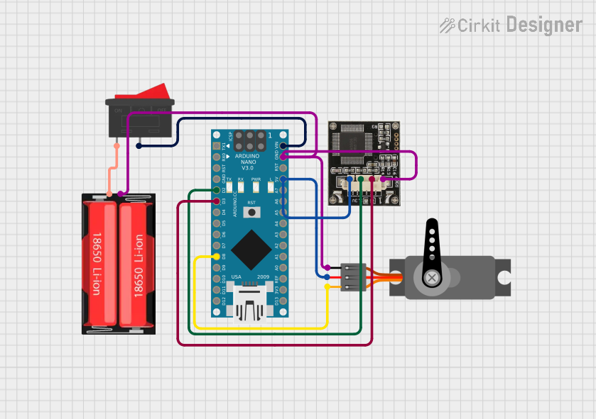
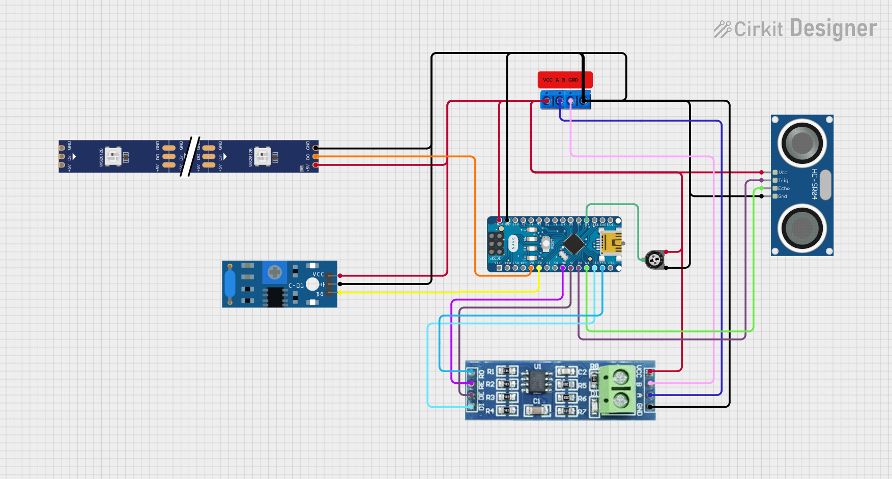
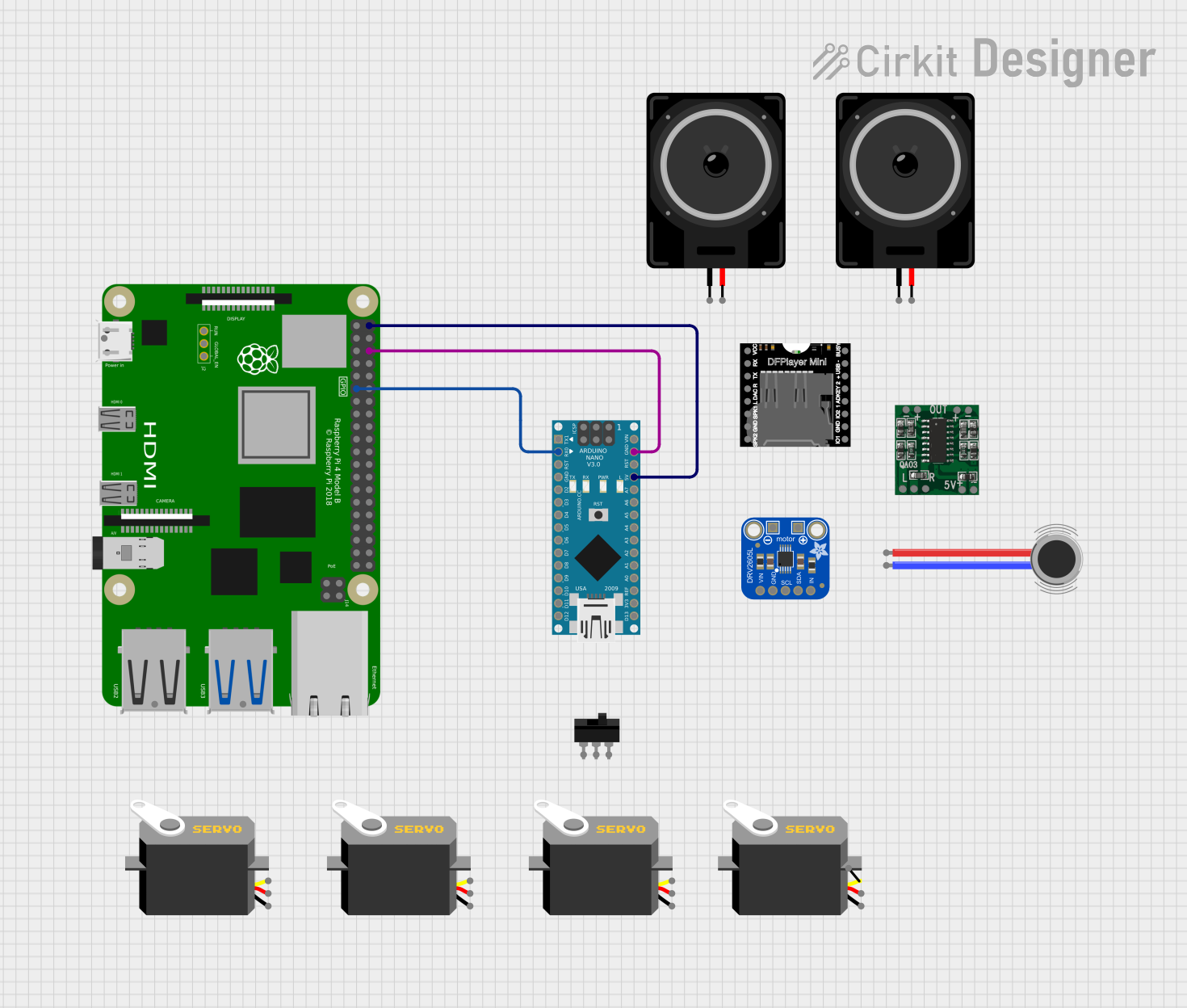
Explore Projects Built with Arduino® Nano R4
Common Applications and Use Cases
- IoT Projects: Ideal for Internet of Things applications due to its compact size and connectivity options.
- Wearable Electronics: Perfect for embedding into small, portable devices.
- Robotics: Used for controlling motors, sensors, and actuators in robotic systems.
- DIY Electronics: Suitable for hobbyists and makers building custom circuits and devices.
- Educational Projects: Widely used in schools and universities for teaching electronics and programming.
Technical Specifications
The following table outlines the key technical details of the Arduino Nano R4:
| Specification | Details |
|---|---|
| Microcontroller | ATmega328P |
| Operating Voltage | 5V |
| Input Voltage (VIN) | 7-12V |
| Digital I/O Pins | 14 (6 of which provide PWM output) |
| Analog Input Pins | 8 |
| DC Current per I/O Pin | 40 mA |
| Flash Memory | 32 KB (2 KB used by bootloader) |
| SRAM | 2 KB |
| EEPROM | 1 KB |
| Clock Speed | 16 MHz |
| USB Connectivity | Micro-USB port for programming and power supply |
| Dimensions | 45 mm x 18 mm |
| Weight | 7 g |
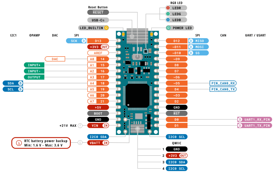
Pin Configuration and Descriptions
The Arduino Nano R4 has a total of 30 pins. The table below provides a detailed description of the pin configuration:
| Pin | Type | Description |
|---|---|---|
| VIN | Power Input | External power input (7-12V). |
| GND | Ground | Ground connection. |
| 5V | Power Output | Regulated 5V output. |
| 3.3V | Power Output | Regulated 3.3V output. |
| A0-A7 | Analog Input | Analog input pins (10-bit resolution). |
| D0-D13 | Digital I/O | Digital input/output pins. |
| PWM | Digital Output | Pins D3, D5, D6, D9, D10, and D11 support PWM output. |
| RX (D0) | Serial Input | UART receive pin for serial communication. |
| TX (D1) | Serial Output | UART transmit pin for serial communication. |
| RESET | Reset | Resets the microcontroller. |
| ICSP | Programming | In-Circuit Serial Programming header for flashing the microcontroller. |
Usage Instructions
How to Use the Arduino Nano R4 in a Circuit
Powering the Board:
- Connect the board to your computer using a Micro-USB cable for programming and power.
- Alternatively, supply power through the VIN pin (7-12V) or the 5V pin (regulated 5V).
Programming the Board:
- Install the Arduino IDE from the official Arduino website.
- Select "Arduino Nano" as the board type and "ATmega328P" as the processor in the Tools menu.
- Write your code in the Arduino IDE and upload it to the board via the Micro-USB connection.
Connecting Components:
- Use the digital pins (D0-D13) for digital input/output operations.
- Use the analog pins (A0-A7) for reading analog signals (e.g., from sensors).
- Connect external modules (e.g., motors, LEDs, sensors) to the appropriate pins, ensuring current and voltage limits are not exceeded.
Important Considerations and Best Practices
- Power Supply: Ensure the input voltage does not exceed the specified range (7-12V) to avoid damaging the board.
- Pin Current Limits: Do not exceed 40 mA per I/O pin to prevent overheating or damage.
- Static Protection: Handle the board with care to avoid static discharge, which can damage the microcontroller.
- Code Optimization: Optimize your code to make efficient use of the limited SRAM and Flash memory.
Example Code for Arduino Nano R4
The following example demonstrates how to blink an LED connected to pin D13:
// Blink an LED connected to pin D13
// This example toggles the LED on and off every second.

void setup() {
  pinMode(13, OUTPUT); // Set pin D13 as an output
}

void loop() {
  digitalWrite(13, HIGH); // Turn the LED on
  delay(1000);            // Wait for 1 second
  digitalWrite(13, LOW);  // Turn the LED off
  delay(1000);            // Wait for 1 second
}
Troubleshooting and FAQs
Common Issues and Solutions
The board is not detected by the computer:
- Ensure the Micro-USB cable is functional and supports data transfer.
- Check that the correct board and port are selected in the Arduino IDE.
Code upload fails:
- Verify that the correct processor ("ATmega328P") is selected in the Tools menu.
- Press the RESET button on the board before uploading the code.
Components connected to the board are not working:
- Double-check the wiring and ensure components are connected to the correct pins.
- Verify that the power supply is sufficient for the connected components.
The board overheats:
- Ensure the input voltage does not exceed 12V.
- Check that the current drawn by connected components does not exceed the board's limits.
FAQs
Q: Can the Arduino Nano R4 be powered by a battery?
A: Yes, you can power the board using a battery by connecting it to the VIN pin (7-12V) or the 5V pin (regulated 5V).
Q: Is the Arduino Nano R4 compatible with shields?
A: The Nano R4 is not directly compatible with standard Arduino shields due to its smaller size, but it can be used with custom shields or breakout boards designed for the Nano form factor.
Q: Can I use the Arduino Nano R4 for wireless communication?
A: The Nano R4 does not have built-in wireless capabilities, but you can connect external modules (e.g., Bluetooth or Wi-Fi) to enable wireless communication.
Q: How do I reset the board?
A: Press the RESET button on the board to restart the microcontroller.