How to Use DC-DC Step down buck converter 20A: Examples, Pinouts, and Specs
Introduction
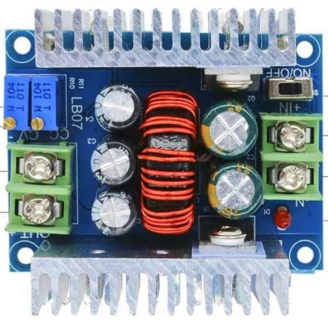
The TNK DC-DC Step Down Buck Converter 20A is a versatile and efficient power supply component designed to convert a higher DC voltage to a lower DC voltage. With a maximum current output of 20A, this buck converter is ideal for applications requiring substantial power delivery while maintaining high efficiency. Common use cases include powering microcontrollers, sensors, and other electronic devices from a higher voltage source, such as a battery or a solar panel.
Explore Projects Built with DC-DC Step down buck converter 20A


Explore Projects Built with DC-DC Step down buck converter 20A
Technical Specifications
Key Technical Details
| Parameter | Value |
|---|---|
| Input Voltage Range | 6V - 40V |
| Output Voltage Range | 1.2V - 36V |
| Maximum Output Current | 20A |
| Efficiency | Up to 95% |
| Switching Frequency | 150kHz |
| Operating Temperature | -40°C to +85°C |
| Dimensions | 60mm x 53mm x 22mm |
Pin Configuration and Descriptions
| Pin Number | Pin Name | Description |
|---|---|---|
| 1 | VIN | Input voltage (6V - 40V) |
| 2 | GND | Ground |
| 3 | VOUT | Output voltage (1.2V - 36V) |
| 4 | ADJ | Output voltage adjustment (via potentiometer) |
Usage Instructions
How to Use the Component in a Circuit
Connect the Input Voltage:
- Connect the positive terminal of your power source to the
VINpin. - Connect the negative terminal of your power source to the
GNDpin.
- Connect the positive terminal of your power source to the
Connect the Output Voltage:
- Connect the
VOUTpin to the load (the device you want to power). - Ensure the
GNDpin is also connected to the ground of the load.
- Connect the
Adjust the Output Voltage:
- Use the potentiometer connected to the
ADJpin to set the desired output voltage. - Measure the output voltage with a multimeter to ensure it is set correctly.
- Use the potentiometer connected to the
Important Considerations and Best Practices
- Heat Dissipation: Ensure adequate cooling for the converter, especially when operating at high currents. Use a heatsink or active cooling if necessary.
- Input Voltage: Always ensure the input voltage is within the specified range (6V - 40V) to prevent damage to the converter.
- Output Voltage Adjustment: Adjust the output voltage slowly and carefully to avoid overshooting the desired voltage.
- Load Connection: Ensure the load does not exceed the maximum current rating of 20A to prevent overheating and potential damage.
Example: Connecting to an Arduino UNO
To power an Arduino UNO using the TNK DC-DC Step Down Buck Converter, follow these steps:
Set the Output Voltage:
- Adjust the output voltage to 5V using the potentiometer.
Connect the Converter to the Arduino:
- Connect the
VOUTpin to the 5V pin on the Arduino. - Connect the
GNDpin to the GND pin on the Arduino.
- Connect the
Connect the Input Voltage:
- Connect a suitable power source (e.g., a 12V battery) to the
VINandGNDpins of the converter.
- Connect a suitable power source (e.g., a 12V battery) to the
// Example code to blink an LED connected to pin 13 on the Arduino UNO

void setup() {
  pinMode(13, OUTPUT); // Set pin 13 as an output
}

void loop() {
  digitalWrite(13, HIGH); // Turn the LED on
  delay(1000);            // Wait for 1 second
  digitalWrite(13, LOW);  // Turn the LED off
  delay(1000);            // Wait for 1 second
}
Troubleshooting and FAQs
Common Issues Users Might Face
No Output Voltage:
- Solution: Check the input voltage to ensure it is within the specified range. Verify all connections are secure and correct.
Overheating:
- Solution: Ensure adequate cooling. Check if the load current exceeds 20A. Reduce the load if necessary.
Output Voltage Fluctuations:
- Solution: Verify the stability of the input voltage. Ensure the potentiometer is not loose and is set correctly.
FAQs
Q1: Can I use this converter to charge a battery?
- A1: Yes, but ensure the output voltage is set according to the battery's charging requirements and use appropriate charging circuitry to prevent overcharging.
Q2: What happens if I exceed the maximum input voltage?
- A2: Exceeding the maximum input voltage (40V) can damage the converter. Always ensure the input voltage is within the specified range.
Q3: Can I use this converter with an AC power source?
- A3: No, this converter is designed for DC input only. Using an AC power source will damage the converter.
By following this documentation, users can effectively utilize the TNK DC-DC Step Down Buck Converter 20A in their projects, ensuring efficient and reliable power delivery.