How to Use 220V AC Optocoupler Isolation Module: Examples, Pinouts, and Specs
Introduction
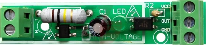
The 220V AC Optocoupler Isolation Module (Manufacturer: Robu, Part ID: WC_PAN_05) is a device designed to provide electrical isolation between high-voltage AC circuits and low-voltage control circuits. It uses an optocoupler to transmit signals optically, ensuring that there is no direct electrical connection between the two circuits. This isolation protects sensitive low-voltage components from high-voltage surges and noise, making it ideal for industrial and home automation applications.
Explore Projects Built with 220V AC Optocoupler Isolation Module

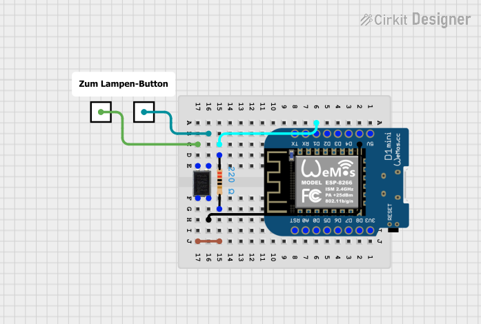
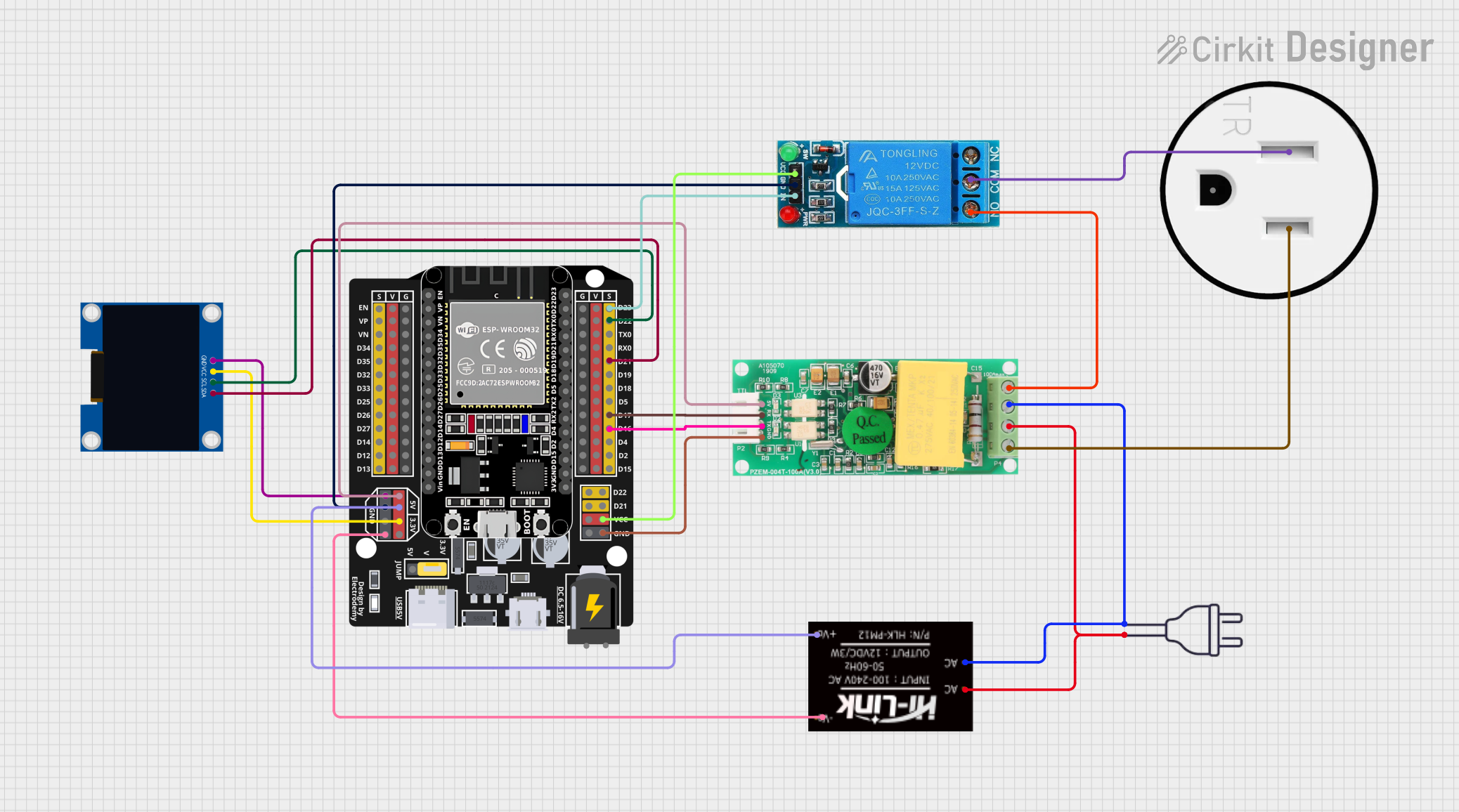

Explore Projects Built with 220V AC Optocoupler Isolation Module
Common Applications and Use Cases
- Industrial Automation: Isolating control systems from high-voltage machinery.
- Home Automation: Interfacing with high-voltage appliances like lights, fans, or heaters.
- Microcontroller Projects: Safely connecting microcontrollers (e.g., Arduino, Raspberry Pi) to AC-powered devices.
- Signal Isolation: Preventing ground loops and electrical noise in sensitive circuits.
Technical Specifications
Key Technical Details
| Parameter | Value |
|---|---|
| Operating Voltage (Input) | 220V AC |
| Output Voltage (Control) | 3.3V to 5V DC |
| Isolation Voltage | ≥ 2500V |
| Optocoupler Type | Phototransistor-based |
| Response Time | ≤ 20 µs |
| Dimensions | 50mm x 25mm x 15mm |
| Mounting Type | PCB Mountable |
| Operating Temperature | -25°C to +85°C |
Pin Configuration and Descriptions
Input Side (High Voltage AC)
| Pin Name | Description |
|---|---|
| AC IN+ | High-voltage AC input (Live wire) |
| AC IN- | High-voltage AC input (Neutral wire) |
Output Side (Low Voltage Control)
| Pin Name | Description |
|---|---|
| VCC | Positive DC supply (3.3V to 5V) |
| GND | Ground (0V reference) |
| OUT | Digital output signal (High/Low) |
Usage Instructions
How to Use the Component in a Circuit
Connect the High-Voltage Side:
- Connect the AC IN+ pin to the live wire of the 220V AC source.
- Connect the AC IN- pin to the neutral wire of the 220V AC source.
- Ensure proper insulation and safety precautions when handling high-voltage connections.
Connect the Low-Voltage Side:
- Connect the VCC pin to the 3.3V or 5V DC supply of your microcontroller or control circuit.
- Connect the GND pin to the ground of your control circuit.
- Connect the OUT pin to a digital input pin of your microcontroller.
Verify Connections:
- Double-check all connections before powering the circuit.
- Use a multimeter to ensure there are no short circuits.
Power On:
- Power the high-voltage AC source and the low-voltage DC control circuit.
- The module will output a digital signal (High or Low) on the OUT pin based on the presence of AC voltage.
Important Considerations and Best Practices
- Safety First: Always handle the high-voltage side with care. Use proper insulation and avoid touching live wires.
- Isolation: Ensure that the high-voltage and low-voltage sides are physically separated to prevent accidental contact.
- Load Limitations: This module is designed for signal isolation, not for driving high-power loads directly.
- Pull-Up Resistor: If the output signal is unstable, consider adding a pull-up resistor (e.g., 10kΩ) to the OUT pin.
Example: Connecting to an Arduino UNO
Below is an example of how to use the module with an Arduino UNO to detect the presence of 220V AC.
// Define the pin connected to the OUT pin of the module
const int optoPin = 2; // Digital pin 2 on Arduino

void setup() {
  pinMode(optoPin, INPUT); // Set optoPin as input
  Serial.begin(9600);      // Initialize serial communication
}

void loop() {
  int signal = digitalRead(optoPin); // Read the signal from the module

  if (signal == HIGH) {
    Serial.println("AC Voltage Detected"); // Print message if AC is present
  } else {
    Serial.println("No AC Voltage");       // Print message if AC is absent
  }

  delay(500); // Wait for 500ms before the next reading
}
Troubleshooting and FAQs
Common Issues and Solutions
No Output Signal on the OUT Pin:
- Cause: Incorrect wiring or no AC voltage on the input side.
- Solution: Verify the AC input connections and ensure the AC source is active.
Unstable Output Signal:
- Cause: Electrical noise or insufficient pull-up resistor.
- Solution: Add a pull-up resistor (e.g., 10kΩ) to the OUT pin.
Module Overheating:
- Cause: Prolonged exposure to high temperatures or excessive current.
- Solution: Ensure the module is operated within its specified temperature and voltage limits.
Arduino Not Detecting Signal:
- Cause: Incorrect pin configuration or loose connections.
- Solution: Check the Arduino code and ensure the OUT pin is properly connected to the Arduino.
FAQs
Q1: Can this module be used with a 110V AC source?
A1: No, this module is specifically designed for 220V AC. Using it with 110V AC may result in unreliable operation.
Q2: Is the module suitable for switching high-power loads?
A2: No, this module is intended for signal isolation only. Use a relay or solid-state switch for high-power loads.
Q3: Can I use this module with a Raspberry Pi?
A3: Yes, the module can be used with a Raspberry Pi. Ensure the OUT pin voltage is compatible with the Raspberry Pi's GPIO input levels.
Q4: What is the maximum distance between the high-voltage and low-voltage sides?
A4: The module provides electrical isolation, but for safety, keep the high-voltage and low-voltage sides physically separated by at least a few centimeters.
This concludes the documentation for the 220V AC Optocoupler Isolation Module. Always prioritize safety when working with high-voltage circuits!