How to Use Dc-dc 400W 15A Step-Up Boost Converter: Examples, Pinouts, and Specs
Introduction
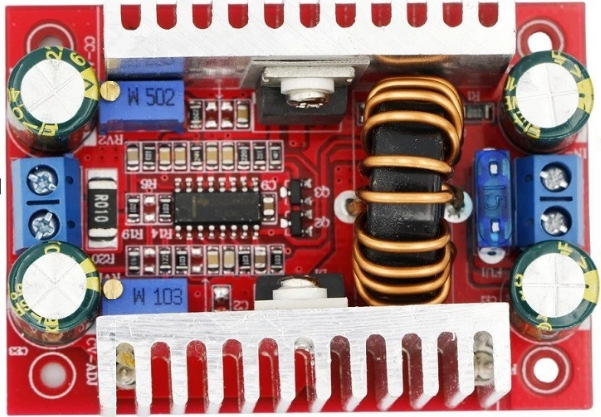
The DC-DC 400W 15A Step-Up Boost Converter is a high-power voltage regulator designed to increase a lower input voltage to a higher, stable output voltage. Manufactured in China, this versatile component is widely used in applications requiring efficient voltage elevation, such as battery-powered systems, solar power setups, LED drivers, and electric vehicle systems. Its robust design supports up to 400W of power and 15A of current, making it suitable for demanding applications.
Explore Projects Built with Dc-dc 400W 15A Step-Up Boost Converter


Explore Projects Built with Dc-dc 400W 15A Step-Up Boost Converter
Technical Specifications
The following table outlines the key technical details of the DC-DC 400W 15A Step-Up Boost Converter:
| Parameter | Value |
|---|---|
| Input Voltage Range | 8V to 60V |
| Output Voltage Range | 10V to 120V |
| Maximum Output Power | 400W |
| Maximum Output Current | 15A |
| Efficiency | Up to 96% |
| Operating Temperature | -40°C to +85°C |
| Dimensions | 130mm x 52mm x 45mm |
| Weight | ~200g |
Pin Configuration and Descriptions
The DC-DC 400W 15A Step-Up Boost Converter has the following input and output connections:
| Pin | Label | Description |
|---|---|---|
| 1 | VIN+ | Positive input voltage terminal |
| 2 | VIN- | Negative input voltage terminal (ground) |
| 3 | VOUT+ | Positive output voltage terminal |
| 4 | VOUT- | Negative output voltage terminal (ground) |
| 5 | ADJ | Potentiometer for adjusting the output voltage |
Usage Instructions
How to Use the Component in a Circuit
Connect the Input Voltage:
- Connect the positive terminal of your power source to the
VIN+pin. - Connect the negative terminal of your power source to the
VIN-pin. - Ensure the input voltage is within the range of 8V to 60V.
- Connect the positive terminal of your power source to the
Connect the Load:
- Connect the positive terminal of your load to the
VOUT+pin. - Connect the negative terminal of your load to the
VOUT-pin.
- Connect the positive terminal of your load to the
Adjust the Output Voltage:
- Use the onboard potentiometer labeled
ADJto set the desired output voltage. - Turn the potentiometer clockwise to increase the output voltage and counterclockwise to decrease it.
- Use a multimeter to monitor the output voltage during adjustment.
- Use the onboard potentiometer labeled
Power On:
- Once all connections are secure, power on the input source.
- Verify the output voltage and current to ensure they meet your requirements.
Important Considerations and Best Practices
- Heat Dissipation: The converter may generate significant heat during operation, especially at high power levels. Use an appropriate heatsink or active cooling to prevent overheating.
- Input Voltage Range: Ensure the input voltage remains within the specified range (8V to 60V) to avoid damage to the converter.
- Output Voltage Limit: Do not exceed the maximum output voltage of 120V or the maximum output current of 15A.
- Polarity: Double-check the polarity of all connections to prevent damage to the converter or connected devices.
- Load Testing: Gradually increase the load to ensure stable operation and avoid sudden surges.
Example: Using with an Arduino UNO
The DC-DC 400W 15A Step-Up Boost Converter can be used to power an Arduino UNO in projects requiring a higher voltage. Below is an example of how to connect the converter to an Arduino UNO:
- Set the output voltage of the converter to 9V using the
ADJpotentiometer. - Connect the
VOUT+pin of the converter to the Arduino's VIN pin. - Connect the
VOUT-pin of the converter to the Arduino's GND pin.
Here is a simple Arduino code snippet to blink an LED while powered by the boost converter:
// Blink an LED connected to pin 13 of the Arduino UNO
// Ensure the boost converter is set to output 9V for safe operation

void setup() {
  pinMode(13, OUTPUT); // Set pin 13 as an output pin
}

void loop() {
  digitalWrite(13, HIGH); // Turn the LED on
  delay(1000);            // Wait for 1 second
  digitalWrite(13, LOW);  // Turn the LED off
  delay(1000);            // Wait for 1 second
}
Troubleshooting and FAQs
Common Issues and Solutions
No Output Voltage:
- Cause: Incorrect input connections or insufficient input voltage.
- Solution: Verify the polarity and ensure the input voltage is within the specified range.
Overheating:
- Cause: Excessive load or inadequate cooling.
- Solution: Reduce the load or add a heatsink/fan for better heat dissipation.
Unstable Output Voltage:
- Cause: Poor input power quality or incorrect potentiometer adjustment.
- Solution: Use a stable power source and carefully adjust the potentiometer.
Output Voltage Exceeds Desired Value:
- Cause: Potentiometer not properly adjusted.
- Solution: Re-adjust the potentiometer while monitoring the output voltage with a multimeter.
FAQs
Q: Can I use this converter with a 12V car battery?
A: Yes, the converter can step up the 12V input to a higher voltage, provided the output power does not exceed 400W.Q: Is the converter suitable for charging batteries?
A: Yes, but ensure the output voltage and current are set according to the battery's specifications.Q: Can I use this converter for audio amplifiers?
A: Yes, the high power and adjustable output voltage make it suitable for powering audio amplifiers.Q: What happens if I exceed the maximum input voltage?
A: Exceeding the input voltage range may damage the converter. Always stay within the specified range.
By following this documentation, you can effectively use the DC-DC 400W 15A Step-Up Boost Converter in your projects while ensuring safe and reliable operation.