
How to Use FFC26 Connector (WATN001002BF): Examples, Pinouts, and Specs
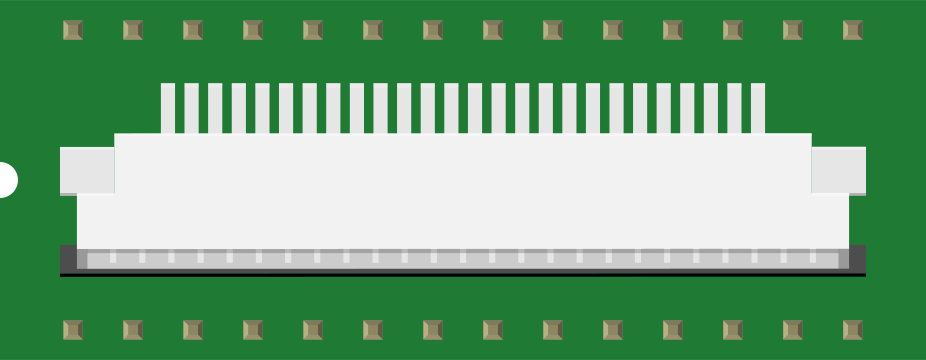
 Design with FFC26 Connector (WATN001002BF) in Cirkit Designer
Introduction
The FFC26 Connector (WATN001002BF) is a flat flexible cable (FFC) connector designed for securely connecting flexible printed circuits (FPCs) to printed circuit boards (PCBs). Its compact design makes it ideal for space-saving applications, particularly in modern electronic devices where miniaturization is critical. This connector is widely used in consumer electronics, industrial equipment, and automotive systems.
Explore Projects Built with FFC26 Connector (WATN001002BF)
 Open Project in Cirkit Designer
 Open Project in Cirkit Designer
 Open Project in Cirkit Designer
 Open Project in Cirkit Designer
Explore Projects Built with FFC26 Connector (WATN001002BF)
Open Project in Cirkit DesignerOpen Project in Cirkit DesignerOpen Project in Cirkit DesignerOpen Project in Cirkit DesignerCommon Applications
- Smartphones, tablets, and other portable devices
- LCD displays and touchscreens
- Printers and scanners
- Automotive infotainment systems
- Industrial control panels
Technical Specifications
Key Technical Details
| Parameter | Value |
|---|---|
| Connector Type | Flat Flexible Cable (FFC) |
| Number of Pins | 26 |
| Pitch (Pin Spacing) | 1.0 mm |
| Mounting Type | Surface Mount Technology (SMT) |
| Operating Voltage | 50V AC/DC |
| Current Rating | 0.5A per pin |
| Operating Temperature | -40°C to +85°C |
| Contact Material | Phosphor Bronze with Gold Plating |
| Insulation Resistance | ≥ 100 MΩ |
| Durability | 20 mating cycles |
Pin Configuration and Descriptions
The FFC26 Connector has 26 pins arranged in a single row with a 1.0 mm pitch. Below is the pin configuration:
| Pin Number | Description |
|---|---|
| 1-26 | Signal or power connections (user-defined based on application) |
Note: The pin assignments are user-defined and depend on the specific circuit design. Ensure proper alignment of the FFC cable with the connector to avoid misconnection.
Usage Instructions
How to Use the FFC26 Connector in a Circuit
Prepare the FFC Cable:
- Ensure the FFC cable is cut to the correct length and the contacts are clean.
- Verify that the cable matches the connector's specifications (e.g., pitch and number of pins).
Mount the Connector:
- Solder the FFC26 Connector onto the PCB using Surface Mount Technology (SMT).
- Ensure proper alignment with the PCB pads to avoid soldering defects.
Insert the FFC Cable:
- Open the connector's locking mechanism (if applicable).
- Insert the FFC cable into the connector, ensuring the contacts are properly aligned.
- Close the locking mechanism to secure the cable.
Verify Connections:
- Use a multimeter to check for continuity between the FFC cable and the PCB.
- Power on the circuit and test the functionality of the connected components.
Important Considerations and Best Practices
- Cable Orientation: Ensure the FFC cable is inserted with the correct orientation (e.g., contact side facing the connector's contacts).
- Soldering: Use appropriate soldering techniques to avoid damaging the connector or PCB.
- Stress Relief: Avoid excessive bending or pulling of the FFC cable to prevent damage to the connector or cable.
- Temperature Limits: Operate the connector within its specified temperature range (-40°C to +85°C).
Example: Connecting to an Arduino UNO
While the FFC26 Connector is not directly compatible with an Arduino UNO, it can be used to interface an FPC-based peripheral (e.g., an LCD display) with the Arduino. Below is an example of how to connect an FPC-based LCD to an Arduino UNO using the FFC26 Connector and a breakout board.
// Example: Interfacing an FPC-based LCD with Arduino UNO
// Ensure the FFC26 Connector is properly soldered to the breakout board
// and the LCD is connected to the Arduino via appropriate pins.

#include <LiquidCrystal.h>

// Initialize the LCD with the pins connected to the Arduino
// (RS, Enable, D4, D5, D6, D7)
LiquidCrystal lcd(7, 8, 9, 10, 11, 12);

void setup() {
  // Set up the LCD's number of columns and rows
  lcd.begin(16, 2);

  // Print a message to the LCD
  lcd.print("Hello, FFC26!");
}

void loop() {
  // No additional code needed for this example
}
Note: Use a breakout board to adapt the FFC26 Connector to standard pin headers for easy connection to the Arduino UNO.
Troubleshooting and FAQs
Common Issues and Solutions
Issue: The FFC cable does not fit into the connector.
- Solution: Verify that the cable matches the connector's specifications (e.g., pitch and number of pins). Ensure the locking mechanism is open before inserting the cable.
Issue: Poor or intermittent connection between the FFC cable and the PCB.
- Solution: Check for proper alignment of the cable with the connector. Clean the cable contacts and ensure the locking mechanism is securely closed.
Issue: The connected device does not function as expected.
- Solution: Verify the pin assignments and ensure the FFC cable is correctly oriented. Use a multimeter to check for continuity and troubleshoot the circuit.
Issue: The connector or cable is damaged during installation.
- Solution: Handle the connector and cable with care. Avoid excessive force when inserting or removing the cable.
FAQs
Q1: Can the FFC26 Connector be used in high-vibration environments?
A1: While the connector is durable, additional measures such as securing the FFC cable with adhesive or clamps are recommended for high-vibration environments.
Q2: Is the FFC26 Connector compatible with 0.5 mm pitch cables?
A2: No, the FFC26 Connector is designed for 1.0 mm pitch cables. Using a mismatched cable may result in poor connections or damage.
Q3: How many times can the FFC cable be inserted and removed?
A3: The connector is rated for 20 mating cycles. Exceeding this limit may reduce reliability.
Q4: Can the FFC26 Connector handle power connections?
A4: Yes, the connector can handle up to 0.5A per pin and 50V AC/DC. Ensure the total current does not exceed the connector's rating.
By following this documentation, users can effectively integrate the FFC26 Connector (WATN001002BF) into their designs and troubleshoot common issues.