
How to Use SCA1000: Examples, Pinouts, and Specs
 Design with SCA1000 in Cirkit Designer
Introduction
The SCA1000 is a high-performance, low-power 3D accelerometer manufactured by VTI Technologies. It is designed for motion sensing applications and provides precise measurements of acceleration across three axes (X, Y, and Z). The SCA1000 is widely used in consumer electronics, automotive systems, and industrial applications for motion detection, orientation sensing, and vibration monitoring. Its robust design and high accuracy make it suitable for demanding environments.
Explore Projects Built with SCA1000
 Open Project in Cirkit Designer
 Open Project in Cirkit Designer
 Open Project in Cirkit Designer
 Open Project in Cirkit Designer
Explore Projects Built with SCA1000
Open Project in Cirkit DesignerOpen Project in Cirkit DesignerOpen Project in Cirkit DesignerOpen Project in Cirkit DesignerCommon Applications:
- Automotive systems (e.g., electronic stability control, rollover detection)
- Industrial equipment monitoring
- Consumer electronics (e.g., gaming devices, smartphones)
- Robotics and drones for motion and orientation sensing
- Vibration analysis and tilt sensing
Technical Specifications
Key Technical Details:
| Parameter | Value |
|---|---|
| Supply Voltage | 3.0V to 3.6V |
| Operating Current | 2.5 mA (typical) |
| Measurement Range | ±2g or ±6g (configurable) |
| Sensitivity | 600 mV/g (±2g mode), 200 mV/g (±6g mode) |
| Output Type | Analog voltage output |
| Operating Temperature Range | -40°C to +125°C |
| Bandwidth | Configurable up to 50 Hz |
| Communication Interface | SPI |
Pin Configuration and Descriptions:
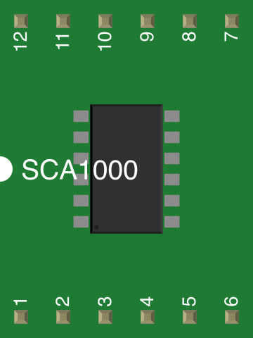
The SCA1000 is typically available in a 12-pin package. Below is the pinout and description:
| Pin Number | Pin Name | Description |
|---|---|---|
| 1 | VDD | Power supply (3.0V to 3.6V) |
| 2 | GND | Ground |
| 3 | CSB | Chip Select for SPI communication |
| 4 | SCK | Serial Clock for SPI |
| 5 | MISO | Master In Slave Out (SPI data output) |
| 6 | MOSI | Master Out Slave In (SPI data input) |
| 7 | XOUT | Analog output for X-axis acceleration |
| 8 | YOUT | Analog output for Y-axis acceleration |
| 9 | ZOUT | Analog output for Z-axis acceleration |
| 10 | BW_SEL | Bandwidth selection |
| 11 | ST | Self-test input |
| 12 | NC | Not connected |
Usage Instructions
How to Use the SCA1000 in a Circuit:
- Power Supply: Connect the VDD pin to a regulated 3.3V power source and the GND pin to ground.
- SPI Communication: Use the CSB, SCK, MISO, and MOSI pins to interface with a microcontroller or processor via SPI. Ensure proper pull-up or pull-down resistors as needed.
- Analog Outputs: The XOUT, YOUT, and ZOUT pins provide analog voltage outputs proportional to the acceleration along each axis. These can be read using an ADC (Analog-to-Digital Converter) on a microcontroller.
- Bandwidth Selection: Use the BW_SEL pin to configure the bandwidth. Refer to the datasheet for specific resistor or voltage configurations.
- Self-Test: The ST pin can be used to initiate a self-test to verify the functionality of the accelerometer.
Important Considerations:
- Decoupling Capacitors: Place a 0.1 µF ceramic capacitor close to the VDD pin to filter noise.
- Mounting Orientation: Ensure the accelerometer is mounted correctly to align with the desired axes of measurement.
- SPI Configuration: Configure the SPI interface on the microcontroller with the correct clock polarity and phase (CPOL = 0, CPHA = 0).
- Temperature Effects: The SCA1000 is temperature-compensated, but extreme temperatures may still affect performance slightly.
Example: Connecting SCA1000 to Arduino UNO
Below is an example of how to interface the SCA1000 with an Arduino UNO using SPI:
Circuit Connections:
| SCA1000 Pin | Arduino UNO Pin |
|---|---|
| VDD | 3.3V |
| GND | GND |
| CSB | Pin 10 |
| SCK | Pin 13 |
| MISO | Pin 12 |
| MOSI | Pin 11 |
Arduino Code:
#include <SPI.h>

// Define SCA1000 pins
const int CSB_PIN = 10; // Chip Select pin

void setup() {
  // Initialize SPI communication
  SPI.begin();
  pinMode(CSB_PIN, OUTPUT);
  digitalWrite(CSB_PIN, HIGH); // Set CSB high (inactive)

  Serial.begin(9600); // Initialize serial communication
}

void loop() {
  // Example: Read data from the SCA1000
  digitalWrite(CSB_PIN, LOW); // Activate the SCA1000
  byte response = SPI.transfer(0x00); // Send dummy byte to receive data
  digitalWrite(CSB_PIN, HIGH); // Deactivate the SCA1000

  // Print the received data
  Serial.print("Received Data: ");
  Serial.println(response, HEX);

  delay(1000); // Wait for 1 second
}
Troubleshooting and FAQs
Common Issues:
No Output from Analog Pins:
- Ensure the power supply voltage is within the specified range (3.0V to 3.6V).
- Verify that the accelerometer is properly connected to the circuit.
- Check for loose or incorrect wiring.
SPI Communication Fails:
- Confirm that the SPI clock polarity and phase settings match the SCA1000's requirements.
- Ensure the CSB pin is toggled correctly during communication.
- Check for noise or interference on the SPI lines.
Inaccurate Measurements:
- Verify the mounting orientation of the accelerometer.
- Ensure the bandwidth selection is appropriate for the application.
- Check for external vibrations or shocks affecting the readings.
FAQs:
Q: Can the SCA1000 measure static acceleration (e.g., gravity)?
A: Yes, the SCA1000 can measure static acceleration, such as gravity, making it suitable for tilt sensing applications.
Q: How do I switch between ±2g and ±6g measurement ranges?
A: The measurement range is configured via SPI commands. Refer to the datasheet for the specific register settings.
Q: What is the purpose of the self-test pin (ST)?
A: The self-test pin allows users to verify the functionality of the accelerometer by applying a known stimulus to the sensor.
Q: Can I use the SCA1000 with a 5V microcontroller?
A: Yes, but you will need level shifters or voltage dividers to interface the 3.3V SCA1000 with 5V logic levels.
This concludes the documentation for the SCA1000 3D accelerometer. For further details, refer to the official datasheet provided by VTI Technologies.